






Selecting the right active balancing BMS requires matching power conversion topology with cell capacity, discharge rates, and thermal limits. Hardware engineers and procurement managers must evaluate four core parameters:
- Current Scaling: Match balancing current to cell capacity (Ah). Use 1A per 100Ah for grid-tied energy storage systems (ESS). Use 0.5A to 1.5A for drone packs.
- Topology Type: Pick flying capacitors for low-voltage deltas. Use inductive magnetic shuttling for constant current. Choose bidirectional DC-DC converters for high-voltage series strings (16S to 240S).
- AFE Signal Protection: Verify hardware low-pass filters. Noise from high-frequency switching can corrupt Analog Front End (AFE) readings.
- Quiescent Current: Keep sleep-mode drain below 10 µA. This prevents total battery discharge during transit.
Small packs under 50Ah run fine on passive boards. However, high-capacity LiFePO4 and NMC packs need a dedicated active balancing BMS. It prevents cell drift, stops early low-voltage cutoffs, and boosts overall energy density.

Key Parameters for Selecting an Active Balancing BMS
Matching Balancing Current to Cell Capacity
Balancing current depends on cell capacity and charge time. Passive resistors bleed excess energy as heat at 30mA to 200mA. On a 300Ah cell, a 1% imbalance equals 3Ah. A passive balancer takes 30 hours to fix this gap. A 3A active balancing BMS resolves it in one hour.
High current creates heat. Continuous 5A balancing in IP67 sealed boxes causes thermal stress near MOSFETs and inductors. Thermal runaway becomes a real risk. AYAA TECH solves this by spreading MOSFETs and sense resistors across multi-layer PCBs. We apply conductive gels and aluminum or copper heat spreaders to drop internal temperatures.
Evaluating Power Topologies

Understanding the core active balancing technology starts with power conversion topology, which dictates transfer speed and efficiency.
- Switched Capacitor (Flying Capacitor): Toggles capacitors between adjacent cells. It is low cost and generates zero magnetic noise. However, speed drops as cell voltages align (ΔV → 0).
- Inductive Magnetic Shuttling: Stores energy in magnetic fields (E = ½ L I2). It delivers constant multi-amp current regardless of voltage deltas.
- Bidirectional DC-DC Converters: Move energy between single cells and the main high-voltage bus. It bypasses step-by-step transfers. This makes it ideal for 16S to 240S peak shaving systems.
Setting Activation Voltage Thresholds
An active balancing BMS must operate inside strict voltage windows. LiFePO4 cells have a flat discharge plateau between 3.20V and 3.35V. Voltage variations here do not equal true capacity gaps.
Balancing inside this flat zone wastes energy. Set your active balancing BMS to activate above 3.40V during charge. Use a voltage delta (ΔV) threshold of 0.01V to 0.02V. Stop balancing when ΔV reaches 0.005V to prevent switch oscillation.
Seeking High-Efficiency BMS Hardware for Industrial Battery Packs?
Explore Product CatalogEngineering Risks and Integration Pitfalls
Controlling PWM Noise and AFE Sampling Errors
High-frequency PWM switching (100kHz to 500kHz) generates electrical noise on sense leads. This noise corrupts AFE voltage readings.
Engineering Note: PWM switching noise causes false ADC readings. The BMS may trigger false overvoltage shutdowns during normal operations.
Hardware must include onboard RC low-pass filters on every cell tap. Heavy loads cause up to 5% State of Charge (SOC) estimation errors on standard boards. AYAA TECH uses advanced filtering to keep SOC error below ≤ 3%.
Unmanned aerial systems (UAS) need seamless telemetry. An AYAA TECH SmartBMS connects directly to open-source flight control systems like ArduPilot and PX4 over CANbus. No custom drivers needed.
Preventing Storage Drain from Quiescent Current
An active balancing BMS draws continuous power to monitor voltage gaps. Without deep sleep modes, quiescent current (1mA to 15mA) drains packs during warehouse storage.
Engineering Note: Unmonitored active circuits ruin stored batteries. If one cell self-discharges faster, the balancer drains neighboring cells to match it. This drags the entire pack to zero volts.
Select an active balancing BMS with a sleep mode under 10 µA. The circuit must sleep when voltages drop below 2.80V or when idle for 24 hours.
Stopping Internal Resistance Energy Ping-Ponging
High internal resistance (Rint) causes dynamic voltage drop under load (V = Vocv – I · Rint). Two cells with equal capacity show different voltages under heavy discharge.
Basic balancers misread this voltage drop as a capacity imbalance. They shuttle charge into the high-resistance cell, then pull it back out when the load stops. This ping-ponging wastes cycle life and generates heat. Choose an active balancing BMS with dynamic I · R compensation.
B2B Application Selection Matrix

Use this comparison matrix to select the right active balancing BMS configuration for your project requirements.
| 애플리케이션 | Pack Setup | Recommended Balancing Current | Core Hardware Priority | Key Protocol & Feature |
|---|---|---|---|---|
| Heavy UAVs & Drones | 12S – 24S LiPo / NMC | 0.5A – 1.5A Active | Lightweight PCB, AFE noise filter | Open-source Flight Control Support (ArduPilot/PX4) |
| Industrial Energy Storage (ESS) | 16S – 240S LiFePO4 | 2A – 5A Bidirectional | Multi-layer heat spreaders, >90% efficiency | Multi-protocol CANbus / RS485 (Victron, Deye, SMA) |
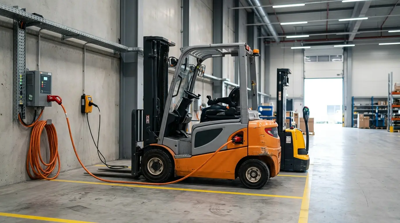
| AGVs & Forklifts | 8S – 24S LiFePO4 / LTO | 1A – 2A Inductive | Shock resistance, fast charge handling | J1939 CAN / IP67 Enclosure |
Matching these parameters ensures high cycle life and lower warranty costs.
Supply Chain ROI and Cost Analysis
An active balancing BMS costs 30% to 100% more than a passive board. However, evaluating total ROI requires looking at battery cycle life.
Active balancing extends pack life by 15% to 30% on high-capacity systems. It prevents weak cells from triggering early low-voltage shutdowns. For a 100kWh ESS container, adding three years of service life offsets the initial hardware cost easily.
B2B buyers need vendors who scale from design to mass production. AYAA TECH manufactures everything from basic PCM boards and hardware BMS to custom SmartBMS units and complete Battery Pack assemblies. We help engineering teams move from prototype testing to full production without vendor switching.
Need Custom Active Balancing or B2B Power System Engineering?
Consult a Battery ArchitectFrequently Asked Questions
Allocate 1A of balancing current per 100Ah of cell capacity. A 200Ah to 300Ah ESS module needs a 2A to 3A balancer. This fixes a 1% to 2% SOC gap during a standard 2-to-4-hour charge window. Smaller 20Ah to 50Ah drone packs run well on 0.5A to 1A active currents.
No. Active balancing equalizes terminal voltages, but it cannot restore lost chemical capacity. It also cannot fix high internal resistance (Rint). A degraded cell still drops fast under load and triggers early system shut-offs.
High-frequency PWM switching (100kHz to 500kHz) generates electromagnetic noise. This noise creates voltage ripples on AFE sense leads. The ADC then reads incorrect voltages. Use a BMS built with onboard RC filters to avoid false fault trips.
Set active balancing to activate above 3.40V per cell. Trigger balancing when the voltage delta (ΔV) hits 0.01V to 0.02V. Balancing below 3.35V wastes energy because LiFePO4 voltage curves are completely flat in that zone.
Balancing circuits draw continuous standby power. Without a deep sleep mode (<10 µA), this drain empties the pack over months. If one cell self-discharges faster, the balancer continuously pulls power from neighboring cells to match it. This drags the entire battery down to zero volts.
Use passive balancing on small packs under 50Ah built with Grade-A matched cells. Passive boards cost less and generate zero switching noise. They use fewer components, which improves total hardware reliability (MTBF) on simple builds.
Yes. Sub-zero temperatures (<0°C) slow lithium intercalation into graphite anodes. If an active balancer pushes 3A to 5A into a cold cell during charging, localized current can exceed safe absorption limits. This causes lithium plating and raises thermal runaway risks. Always verify that your BMS lowers balancing current at cold temperatures.
Facing Integration Challenges in Your Heavy-Duty Battery Architecture?
Contact Our Engineering TeamReferences
- Analog Devices Inc. (ADI): LTC3300-1 High Efficiency Bidirectional Multicell Battery Balancer Technical Documentation.
- Monolithic Power Systems (MPS): Application Note AN142: Active Balancing Solutions for High-Cell-Count Lithium-Ion Battery Packs.
- IEEE Transactions on Power Electronics: Comparative Evaluation and Topology Selection of Active Cell Balancing Circuits for Electric Vehicles and Energy Storage Systems.
- ISO 26262-10: Road vehicles — Functional safety — Part 10: Guideline on ISO 26262 for Battery Management Systems.
- IEC 62619: Secondary cells and batteries containing alkaline or other non-acid electrolytes – Safety requirements for secondary lithium cells and batteries, for use in industrial applications.