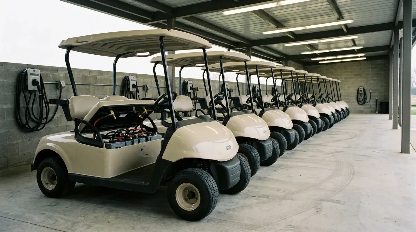
A golf cart pre-charge circuit stops inrush current from welding solenoids and tripping your BMS. Motor controllers contain large filter capacitors that act as dead shorts when empty. Connecting a battery directly pulls hundreds of amps within microseconds. This surge erodes contact plates and causes nuisance trips on lithium packs.
Choosing the right setup means matching resistor resistance and wattage to your pack voltage and controller capacitance. Sizing typically requires a 250-ohm to 1,000-ohm wirewound resistor across the main solenoid lugs. This safely charges capacitors to over 90% voltage before the main contactor closes. For fleet operators, proper selection prevents welded contacts, stops BMS shutoffs, and eliminates costly warranty repairs.

What Happens Without a Golf Cart Pre-Charge Circuit?
The Inrush Current Spike in Controller Capacitors
Motor controllers rely on internal DC-link electrolytic capacitors. These components smooth out voltage ripples during heavy acceleration. When the vehicle is turned off, the capacitors drop to zero volts.
Connecting an uncharged system triggers Ohm’s Law immediately. Very little resistance limits the resulting current spike. Cable resistance and capacitor internal resistance often total under 50 milliohms.
On a 48V battery pack, the peak current easily exceeds 800 amps. This rapid surge creates an intense electrical arc between the contact plates. Over time, recurring arcs vaporize contact material and leave deep pits. Eventually, the extreme heat melts the metal and welds the solenoid shut.
Why Lithium Conversions Magnify Inrush Hazards
Traditional lead-acid batteries have relatively high internal resistance. Pack voltage naturally sags when hit with an inrush spike, dampening the peak current. Lithium iron phosphate (LiFePO4) packs change this dynamic completely.
Lithium cells feature negligible internal resistance. They deliver maximum current almost instantly. As a result, the current rise rate is much steeper than with lead-acid.
This sudden surge creates trouble for the 배터리 관리 시스템. A quality BMS monitors discharge current to protect its internal MOSFETs. An empty controller pulling hundreds of amps looks identical to a direct short circuit. The BMS triggers short-circuit protection and shuts down power before the cart can move.
Engineering Note: Never bypass BMS short-circuit protection to force a controller to turn on. Stretching the detection window creates an extreme fire hazard if a real wiring short occurs downstream.
How Pre-Charge Works in Low-Speed Vehicles
Passive Precharge: The Resistor Across the Solenoid
The standard setup uses a heavy-duty wire-wound resistor. Technicians bolt this resistor directly across the two main solenoid lugs.

Flipping the run switch sends a small current through the resistor. This trickle current charges the controller capacitors steadily. Turning the key energizes the solenoid coil, pulling the heavy internal contacts shut. Since capacitor voltage matches battery voltage, no arcing occurs across the plates.
A complete circuit also requires a coil suppression diode across the small terminals. Collapsing magnetic fields produce inductive voltage spikes exceeding 200V when the solenoid opens. A standard flyback diode clamps this kickback safely. This protects sensitive switches and electronic pedal inputs from voltage damage.
Passive Resistors vs. Active Smart Systems
Passive pre-charge setups rely on a permanently wired resistor across the contactor lugs. They are inexpensive, but they conduct current continuously while the battery stays connected. If a controller fails short internally, the resistor absorbs full voltage and overheats.
Active pre-charge designs use dedicated relays or timed switching circuits. The circuit activates for a brief window during startup. It monitors downstream voltage and engages the main contactor once safe levels are reached. The pre-charge path then disconnects completely during normal vehicle operation.
Field data shows passive resistors work well for standard lead-acid maintenance. However, they create long-term reliability risks on commercial lithium retrofits. Without a manual cut-off, a passive resistor slowly drains idle lithium packs. For commercial fleets, use a mechanical isolator or switch to active BMS pre-charge.
Tired of Welded Contactors & Nuisance BMS Trips?
Explore AYAA TECH Smart BMS SeriesHow to Select Your Golf Cart Pre-Charge Setup
Selecting Resistor Specs by System Voltage
Sizing the resistor requires balancing charge speed against component heat. Choosing a resistance value that is too low overloads the resistor element. Setting the value too high leaves the pre-charge cycle too slow.
Engineers use the RC time constant (τ = R × C) to model this curve. It takes roughly three time constants (3τ) to reach 95% of battery voltage. At this threshold, the main contactor can close without arcing.
The table below outlines proven component pairings across common operating voltages. These values match standard controller capacitance banks found in utility carts.
| System Voltage | Controller Capacitance | Resistor Specification | Precharge Window (3τ) | Contactor Rating |
|---|---|---|---|---|
| 36볼트 | 1,000 µF – 2,200 µF | 250 Ω / 10W wirewound | 0.75s – 1.5s | 200A Continuous |
| 48볼트 | 2,200 µF – 4,700 µF | 470 Ω – 500 Ω / 10W–20W wirewound | 1.0s – 2.3s | 200A or 400A Heavy Duty |
| 72V | 3,300 µF – 6,800 µF | 1,000 Ω (1 kΩ) / 25W aluminum-clad | 1.5s – 3.0s | 400A+ Industrial |
Sticking to these baseline values prevents excessive peak currents during initial engagement. They also ensure the pre-charge finishes before the driver demands full power.
Matching the Resistor to Your Solenoid Size
Standard factory carts use 200A continuous solenoids with 5/16-inch terminals. Common ceramic wirewound resistors with ring terminals bolt directly onto these lugs.
Upgraded carts with high-output controllers require heavy-duty 400A contactors. These contactors feature larger 3/8-inch terminals and face higher vibration loads. For 400A setups, mount an aluminum-housed power resistor directly to the cart chassis. Do not let ceramic resistors hang unsupported between heavy gauge cables.
Passive Parts vs. Integrated Smart BMS Architecture
Sourcing loose resistors and diodes appears economical on an initial parts list. However, loose components increase manual wiring labor during assembly. Reversed diode installations also cause avoidable warranty claims in the field.
Advanced lithium battery packs incorporate active pre-charge circuits directly on the BMS board. The BMS limits startup current electronically before opening high-power output paths.
AYAA TECH integrates active protection directly into smart BMS units and complete packs. AYAA TECH balances thermal dissipation across critical heat sources like MOSFETs and sampling resistors. We use uniform component layouts paired with high-grade thermal silicone pads. When necessary, we use high-conductivity aluminum alloys or copper to improve overall thermal performance.

Operational Pitfalls and How to Prevent Field Failures
Diagnosing an Abnormally Hot Precharge Resistor
Under normal conditions, a pre-charge resistor only carries current for a few seconds. It should remain cool during regular vehicle operation. A smoking or hot resistor indicates that the solenoid contacts failed to close.
If the contactor remains open, driving current routes straight through the small resistor. A 10W resistor exposed to continuous driving current will overheat in seconds. The ceramic housing will glow, melt nearby wire jackets, and fail open.
Engineering Note: A hot pre-charge resistor is always a symptom, not the root cause. Never swap in a higher-wattage resistor to mask the heat. Inspect the solenoid activation coil, key switch wiring, and controller inputs immediately.
The Hidden Threat of Parasitic Battery Drain
Winter storage presents a major risk for lithium carts with passive pre-charge loops. A 470-ohm resistor across an idle 48V battery draws roughly 100 milliamps continuously. Over four weeks, this idle drain pulls more than 70 amp-hours from the battery.
Deep parasitic discharge can drain lithium cells below their critical cutoff thresholds. Severely over-discharged cells suffer internal copper dissolution, permanently ruining the battery pack. Installing a rotary master disconnect switch isolates the battery during prolonged storage.
Tracking real capacity is vital when managing fleet storage schedules across facilities. AYAA TECH addresses this with a high-precision State of Charge algorithm. Our SOC algorithm dynamically adjusts for ambient temperature swings with an error rate ≤ 5%. This precision gives service managers dependable runtime figures and prevents unexpected pack shutdowns.
Upgrading Fleet Vehicles to Lithium? Get Custom Hardware Support.
Request Custom Battery Pack EngineeringFrequently Asked Questions About Golf Cart Pre-Charge Systems
What happens if you run an electric vehicle without a golf cart pre-charge circuit?
Without pre-charge protection, empty controller capacitors draw an instantaneous surge of several hundred amps. This high current creates intense electrical arcing across the solenoid contact plates. Over time, recurring arcs pit the surfaces and weld the contacts together. On lithium conversions, this surge trips the BMS short-circuit protection instantly.
How do I select the right golf cart pre-charge resistor for a 48V system?
A standard 48V golf cart requires a 470-ohm to 500-ohm wirewound resistor. Choose a power rating between 10W and 20W. Pair the resistor with a heavy-duty continuous solenoid rated for 200A or 400A. This combination charges the controller capacitors safely in roughly one to two seconds.
Why is my golf cart pre-charge resistor smoking or getting hot?
Pre-charge resistors are engineered to carry current only during startup. A hot resistor indicates that continuous current is flowing through the bypass loop. This issue typically stems from a failed solenoid coil or welded internal contact plates. It can also point to a shorted motor controller drawing current through the resistor.
Facing Contactor Failures or BMS Integration Bottlenecks?
Consult a Battery Power Architect