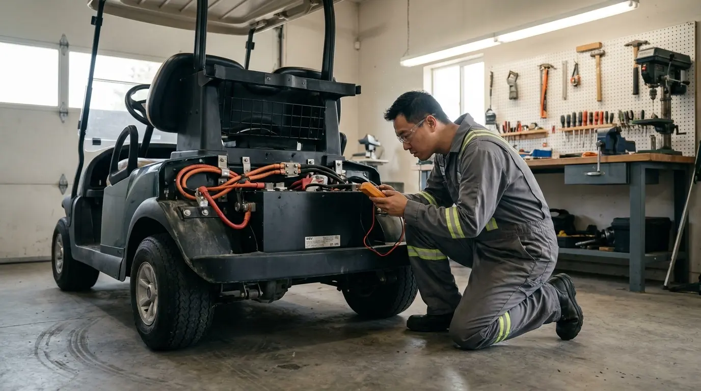
Testing golf cart battery health involves checking resting voltage, load sag, and cell gravity. A battery pack is only as strong as its weakest cell. Static open-circuit voltage provides a fast initial screening. Comparing individual readings against reference tables quickly identifies underperforming units.
A load test demonstrates how each battery performs under operating current. This mechanical or driving test reveals high internal resistance and failing plates. For flooded lead-acid batteries, a hydrometer tests electrolyte specific gravity cell by cell.
Lithium (LiFePO4) battery packs require a different evaluation process. Their flat discharge curve makes digital multimeters ineffective for determining capacity. Instead, technicians access internal telemetry through the smart Battery Management System (BMS).
This step-by-step engineering guide covers both lead-acid and lithium systems. It clarifies whether you should replace a single battery or upgrade the entire pack.
Clear Surface Charge
Multimeter Screening
Dynamic Load Test
Hydrometer Gravity
Smart BMS Telemetry

Tools and Safety Precautions Before You Start
Essential Tools for the Job
You need minimal equipment to begin testing. A digital multimeter with 0.01V resolution is the baseline tool. A temperature-compensating hydrometer is necessary for flooded batteries. A carbon pile load tester provides the most accurate load readings.
Handheld carbon pile testers cost more than digital multimeters. However, you can use the in-cart acceleration method described below for routine checks. Always assemble safety gear before you handle batteries. Gather insulated gloves, safety glasses, a terminal wire brush, baking soda, and distilled water.
Preparing the Cart and Safely Clearing Surface Charge
Park your golf cart on flat, level ground. Turn the key off and shift the tow/run switch to the “Tow” position. Remove all rings, watches, and metal jewelry. Flooded batteries emit flammable hydrogen during charging, so eliminate open flames and sparks.
Next, you must remove false surface charge. Freshly charged batteries display deceptively high voltage readings. These inflated numbers subside as the internal plate chemistry settles. Wait at least six hours after charging, though twelve hours is optimal.
If you must test quickly, turn on the headlights for five minutes. This drains surface charge quickly. Let the pack rest for one hour before recording baseline measurements.
【Engineering Note】 Never evaluate a battery immediately after unplugging the charger. A failing battery can read 12.8V initially, then collapse on a mild incline. That initial reading reflects surface charge rather than true storage capacity.
Step 1: How to Test Golf Cart Battery Health with a Multimeter
Checking the Total Pack Voltage (36V and 48V Systems)
Begin by measuring across the pack’s main positive and main negative terminals. A 36V system usually employs six 6V batteries or three 12V batteries. A 48V system typically features six 8V batteries or four 12V batteries. Set your digital multimeter to DC volts before probing the terminals.
A fully charged, rested 48V lead-acid system should read approximately 50.8V. A healthy 36V system should measure around 38.1V. Values significantly lower than these baseline levels indicate undercharging or degraded capacity.
Testing Each Battery in the Series
Measure each battery individually across its positive and negative posts. Record every reading in sequential order of position in the pack. This pattern tracking highlights individual underperforming units or localized charging failures.
Compare your recorded values across the series string. A variance exceeding 0.2V between individual batteries signals an uneven or lagging unit. Weak batteries degrade the entire string during routine cycling.
Golf Cart Battery Voltage Reference Chart
The table below displays approximate open-circuit voltages at room temperature (80°F / 27°C). Use these benchmarks to estimate individual and pack-level state of charge. Always defer to your manufacturer’s technical data sheet for exact specifications.
| State of Charge | 6V Battery | 8V Battery | 12V Battery | 36V Pack | 48V Pack | Specific Gravity |
|---|---|---|---|---|---|---|
| 100% | 6.35V | 8.47V | 12.70V | 38.1V | 50.8V | 1.277 |
| 75% | 6.22V | 8.30V | 12.45V | 37.3V | 49.8V | 1.238 |
| 50% | 6.10V | 8.13V | 12.20V | 36.6V | 48.8V | 1.200 |
| 25% | 5.98V | 7.97V | 11.95V | 35.9V | 47.8V | 1.170 |
| 0% | 5.85V | 7.80V | 11.70V | 35.1V | 46.8V | 1.130 |
A battery indicating 50% state of charge after a full charge cycle is failing. Lead plate sulfation is the most common cause of this deficit. Insufficient electrolyte levels or faulty charging profiles also accelerate degradation. Always perform a load test before replacing any low-voltage unit.
Step 2: Testing Batteries Under Actual Load
The In-Cart Acceleration Test
Resting open-circuit voltage shows static potential, not deliverable current. You must observe system voltage behavior under significant current draw. Connect a digital voltmeter securely to the main battery pack terminals. Alternatively, monitor an accurate, calibrated in-dash digital voltmeter.
Accelerate the cart briskly on smooth, level ground. Note the lowest voltage recorded during hard acceleration. A healthy 48V pack drops a few volts and promptly stabilizes. If voltage plunges by 15% to 20%, degraded batteries exist in the circuit.
【Engineering Note】 Keep meter test leads completely clear of tires, axles, and drive motors. Never hold manual test probes against terminals while someone operates the vehicle. A slipped probe creates an immediate short circuit across high-amperage terminals. Use bolted ring terminals or switch to a stationary bench load tester.
Using a Handheld Carbon Pile Load Tester
A carbon pile tester applies an adjustable, controlled load to single batteries. This bench method is safer and far more consistent than on-cart driving tests. Adjust the applied load according to the battery manufacturer’s rating. Technicians commonly apply half the Cold Cranking Amps (CCA) or a steady 75-amp load.
Maintain the load continuously for 15 seconds. Record the terminal voltage immediately at the end of the 15-second window. Release the load lever and observe voltage rebound. Track how quickly terminal voltage recovers toward resting potential.

Interpreting the Voltage Drop and Recovery Rate
Healthy deep-cycle batteries retain approximately 80% of nominal voltage under load. Expect at least 5.0V on a 6V unit during testing. Look for at least 6.6V on an 8V battery. A healthy 12V battery should remain above 10.0V while loaded.
Batteries plunging below these threshold values suffer from elevated internal resistance. Voltage recovery speed is equally telling. A sound battery rebounds to baseline within seconds after load release. A degraded unit recovers very sluggishly or stays permanently depressed.
Step 3: Checking Specific Gravity with a Hydrometer (Lead-Acid Only)
Testing Electrolyte Cell by Cell
Put on safety goggles and chemical-resistant gloves before opening vent caps. Remove the cell caps carefully to access liquid electrolyte. Compress the rubber hydrometer bulb and submerge the nozzle into the cell. Draw sufficient fluid to float the internal weighted scale freely.
Read the fluid level directly at eye level. Record each cell’s specific gravity value methodically. Test all cells across the entire battery string. Add distilled water only after completing testing and after full charging.
Fresh water pools at the top and skews hydrometer readings downward. Adding water before charging can cause sulfuric acid to expand and overflow. Apply temperature compensation to your specific gravity readings. Add 0.004 for every 10°F above 80°F.
Subtract 0.004 for every 10°F below 80°F. This adjustment provides an accurate normalized reading.
What the Specific Gravity Readings Mean
A fully charged lead-acid cell delivers a specific gravity between 1.277 and 1.280. Specific gravity decreases proportionally as the cell discharges energy. Cell-to-cell variation matters more than absolute individual readings. A reading difference of 0.030 or greater between cells indicates cell failure.
A cell failing to rise after prolonged charging indicates internal shorting or irreversible sulfation. Such damage compromises the entire battery case. Hydrometers reveal localized faults that multimeters miss. Multimeters only report aggregate series voltage, masking single defective cells.
Need a Modern Replacement for a Tired Lead-Acid Pack?
How to Test Lithium (LiFePO4) Golf Cart Batteries
Why Multimeters Give Misleading Readings on Lithium
Lithium iron phosphate (LiFePO4) chemistry exhibits an exceptionally flat discharge curve. A single cell maintains roughly 3.2V across 80% of its operating cycle. Consequently, a 48V (51.2V 16S) pack looks identical at 80% and 30% capacity. Terminal voltage shifts appreciably only at extreme charge or discharge limits.
Standard lead-acid voltage charts cannot diagnose lithium battery health. Relying on multimeters alone leads to incorrect capacity conclusions. Effective lithium health evaluation requires digital data access.
Reading Battery Health via the BMS (App and Diagnostics)
In lithium systems, the integrated Battery Management System (BMS) acts as the diagnostic instrument. A Smart BMS reports individual cell voltages, pack current, temperatures, and cycle counts. Technicians access this telemetry via Bluetooth apps or CAN/RS485 communication ports.
Examine individual cell voltage balance first. A delta exceeding 50mV to 100mV near full charge indicates cell imbalance. An expanding cell variance over successive months points to a degraded cell. Evaluate thermal differentials across the module during routine charging and discharge cycles.
State of charge (SOC) accuracy is critical for commercial fleet operations. Inaccurate SOC indicators cause unexpected cart shutdowns on steep hills. AYAA TECH Smart BMS units utilize adaptive algorithms with ambient temperature compensation. This engineering design maintains SOC tracking accuracy within a strict 5% error margin.
Thermal dissipation directly governs heavy-duty performance. Power MOSFETs and current shunt resistors generate substantial heat under continuous loads. AYAA designs distribute power components evenly across heavy-copper printed circuit boards. Thermal silicone interfaces and optional aluminum heat spreaders eliminate localized thermal throttling on steep inclines.

Dealing with a 0V Reading (BMS Sleep Mode vs. Failure)
A zero-volt reading at the pack terminals does not necessarily indicate ruined cells. When cell voltages drop below safety limits, the BMS disconnects output MOSFETs. Prolonged storage also triggers BMS low-power sleep mode to preserve internal chemistry. In this state, cell potentials remain stable while exterior terminals measure 0V.
Applying an approved lithium charger often wakes the dormant BMS circuit. Certain lithium packs feature an external manual wake-up button. Depressing this switch restores normal circuit connectivity.
【Engineering Note】 Do not jump-start a 0V lithium pack using lead-acid batteries or unregulated power supplies. Forced charging of severely depleted lithium cells risks copper dendrite formation and thermal runaway. Always contact the battery manufacturer for authorized reactivation procedures.
Deciding Between Single Battery Replacement and a Full Pack Upgrade
The Hidden Costs of Replacing Just One Battery (Impedance Mismatch)
Replacing only one failed battery seems cost-effective initially. However, new batteries possess lower internal resistance and greater storage capacity than older units. In series connections, degraded batteries hit discharge cutoffs first. This dynamic forces older batteries into deep over-discharge cycles.
Simultaneously, the fresh battery never achieves complete charging saturation. Charging current distributes unevenly across mismatched internal resistances. Single-unit replacements typically fail within months, causing premature repeat downtime.
Supply chain factors also disfavor piecemeal replacements. Sourcing identical production lots and date codes proves exceptionally difficult over time. Commercial warranties frequently require balanced pack installations to maintain full coverage. Procuring complete matched sets guarantees uniform electrochemical aging and simplified records.
When purchasing lithium upgrades, always verify compliance documentation early. Request UN 38.3 transport test reports and IEC 62619 industrial safety certificates. Having valid documentation prevents customs holdups and simplifies commercial fleet compliance.
Warning Signs That Warrant a Full Pack Replacement
Replace the entire battery pack when multiple units fail standard load tests. Complete replacement is necessary if your pack exceeds four to five years of service. Inspect physical battery cases for bulging walls, cracked casings, or melted terminals. Persistent cell imbalance despite repeated equalization charging also confirms pack retirement.
If two batteries fail in a six-battery pack, remaining units will fail soon. High-utilization carts and commercial fleets gain substantial ROI from converting to lithium. Lithium systems with Smart BMS monitoring eliminate daily watering, acid corrosion, and range anxiety.
Have a Special Voltage, Size, or Communication Protocol in Mind?
FAQ
1. How do I know if my golf cart needs new batteries?
Noticeable range loss, sluggish hill climbing, and extended charging cycles indicate failing batteries. Batteries that remain warm during charging or read low after full cycles require immediate inspection. Verify battery condition using a multimeter and a mechanical load test.
2. What setting should I use on my multimeter to test golf cart batteries?
Select the Direct Current Voltage (DCV) setting on your meter dial. Look for a capital “V” with straight horizontal lines above it. Select the 20V DC range when testing individual 6V, 8V, or 12V batteries. Select the 200V DC range when measuring complete 36V or 48V series strings.
3. Can you bring dead golf cart batteries back to life?
Recovery depends entirely on internal physical conditions. Mildly sulfated plates or electrolyte-depleted cells often recover through controlled equalization charging and distilled water replenishment. However, batteries with internal short circuits or warped plates cannot be revived. Attempting to charge physically damaged cells wastes energy and creates safety hazards.
4. What is the average lifespan of golf cart batteries?
Properly maintained flooded lead-acid batteries last between four and six years. Lifespan depends heavily on depth of discharge, ambient temperatures, and watering discipline. Modern LiFePO4 lithium batteries typically operate for 3,000 to 5,000 charge cycles. Lithium lifespan corresponds to roughly eight to ten years of standard service.
5. How can I load test golf cart batteries without a special tester?
Perform an in-cart acceleration test on flat asphalt. Charge the pack fully and let it rest overnight. Connect a digital multimeter securely to the main pack terminals. Observe pack voltage sag while applying maximum throttle from a complete stop.
6. Why does my golf cart battery read 12 volts but still die immediately?
Resting voltage indicates surface chemical potential rather than actual stored amp-hour capacity. Severely sulfated battery plates maintain nominal resting voltage without load. However, high internal resistance causes instantaneous voltage collapse under motor load. A formal load test exposes this hidden plate degradation instantly.
7. What is the “90 rule” for golf cart battery maintenance?
The “90 rule” is an informal trade concept rather than an official IEEE engineering standard. Industry technicians recommend avoiding discharges beyond 50% depth of discharge. Recharge batteries promptly after every operating session. Keep electrolyte fluid levels above the lead plates and clean cable connections monthly.