Proper golf cart BMS sizing requires 150A–200A continuous and 300A–400A peak for stock 48V carts. Upgraded carts with high-torque controllers demand 250A to 300A continuous discharge with 600A+ peak thresholds. Most field failures occur during hill climbs or heavy acceleration when uncalibrated boards confuse motor torque demand with short circuits. Unlike stationary energy storage systems, traction packs face severe dynamic electrical and mechanical shocks. This engineering guide details how to calculate your exact continuous and peak current requirements, verify thermal derating, and select the right protection topology.

Golf Cart BMS Sizing: Continuous vs. Peak Current
Continuous current is what your BMS can carry indefinitely. It reflects true thermal equilibrium. Internal silicon must stay below safe operating limits during this state. In contrast, peak current defines a brief pulse. The board can only survive this pulse for a few seconds before heat destroys the switching array.
Peak current ratings on generic datasheets are often marketing traps. Suppliers advertise 400A or 600A peaks without stating duration windows. Many of these boards only survive that current for 100 milliseconds. That is enough time to charge a capacitor. It is not enough time to move a vehicle.
Climbing a turf hill requires peak torque for 5 to 10 seconds. Undersized boards will trip instantly. They may even suffer permanent MOSFET failure. Sound golf cart bms sizing always prioritizes validated continuous amp ratings over vague burst claims.
Engineering Note: Never confuse motor controller AC phase current with battery DC bus current. A controller rated for 400A phase current modulates power through high-frequency switching. At low speeds, battery DC supply current might only hit 150A while phase current reaches 350A. Always size your BMS to match the controller’s maximum DC input current, not the motor’s phase rating.
Traction-grade boards use multi-stage current detection. They separate instant short-circuit cutoffs from long acceleration curves. This keeps the cart moving without compromising electrical safety.
Stepped Overcurrent Protection: Eliminating Hill Trips
Fixed, single-threshold protection ruins vehicle drivability. Traction motors pull heavy current at startup, taper off during acceleration, and settle into low draw while cruising. If your BMS cuts power the moment current rises above continuous ratings, the cart will stall on small inclines.
Industrial packs demand an inverse-time or stepped Overcurrent Protection (OCP) curve. The table below outlines the current tiers required to protect silicon while allowing normal vehicle operation.
| Protection Tier | Current Threshold (% of Continuous) | Permissible Duration | Primary Protection Objective |
|---|---|---|---|
| Tier 1: Continuous | 100% (e.g., 200A) | Indefinite (Steady State) | Keeps junction and busbar temps < 85°C |
| Tier 2: Incline / Surge | 150%–200% (e.g., 300A–400A) | 3 to 10 Seconds | Delivers torque for hills and acceleration |
| Tier 3: Inrush / Stall | 250%–350% (e.g., 500A–700A) | 200 to 500 Milliseconds | Protects against locked-rotor motor stalls |
| Tier 4: Dead Short | > 500% (e.g., 1,000A+) | < 100 Microseconds | Prevents cell rupture and thermal runaway |
This tiered structure mirrors the thermal capacity of the internal switches. Tier 2 absorbs temporary heat during heavy hill climbs. Tier 4 fires ultra-fast hardware comparators. These shut down gate drivers within microseconds to prevent fires during dead shorts.

A Practical Framework for Golf Cart BMS Sizing by Powertrain
Vehicle weight, terrain, and controller capacity dictate electrical demand. A standard two-passenger cart weighs roughly 450 kg with riders. Cruising at 24 km/h (15 mph) on smooth asphalt consumes 2.0 kW to 2.5 kW.
On a 51.2V LiFePO4 battery pack, 2.5 kW requires roughly 49A of continuous current. Soft turf changes the equation. Grass increases rolling resistance by up to 60%. A lifted four-seat cart with 23-inch tires climbing a grade demands 10 kW to 14 kW. That pushes battery DC draw past 270A.
Match your vehicle setup against the benchmark values below to establish your baseline hardware requirements.
| Vehicle Configuration | Motor & Controller Setup | Recommended Continuous BMS | Required Peak Amps (3–10s) | Minimum Cable Size |
|---|---|---|---|---|
| Stock Fleet 48V (2-Seat) | Stock AC/DC Motor, 250A Controller | 150A | 300A | 2 AWG (35 mm²) |
| Modified 48V (4–6 Seat, Lifted) | Stock or Mild Upgrade, 300A–350A Controller | 200A | 400A–450A | 1/0 AWG (50 mm²) |
| High-Output 48V (Off-Road) | Aftermarket Motor, 400A–600A Controller | 250A–300A | 600A–800A | 2/0 AWG (70 mm²) |
| Commercial Utility 48V–72V | Heavy-Duty Traction, 500A+ Controller | 300A (or Contactor Unit) | 750A–1,000A | 3/0 AWG (95 mm²) |
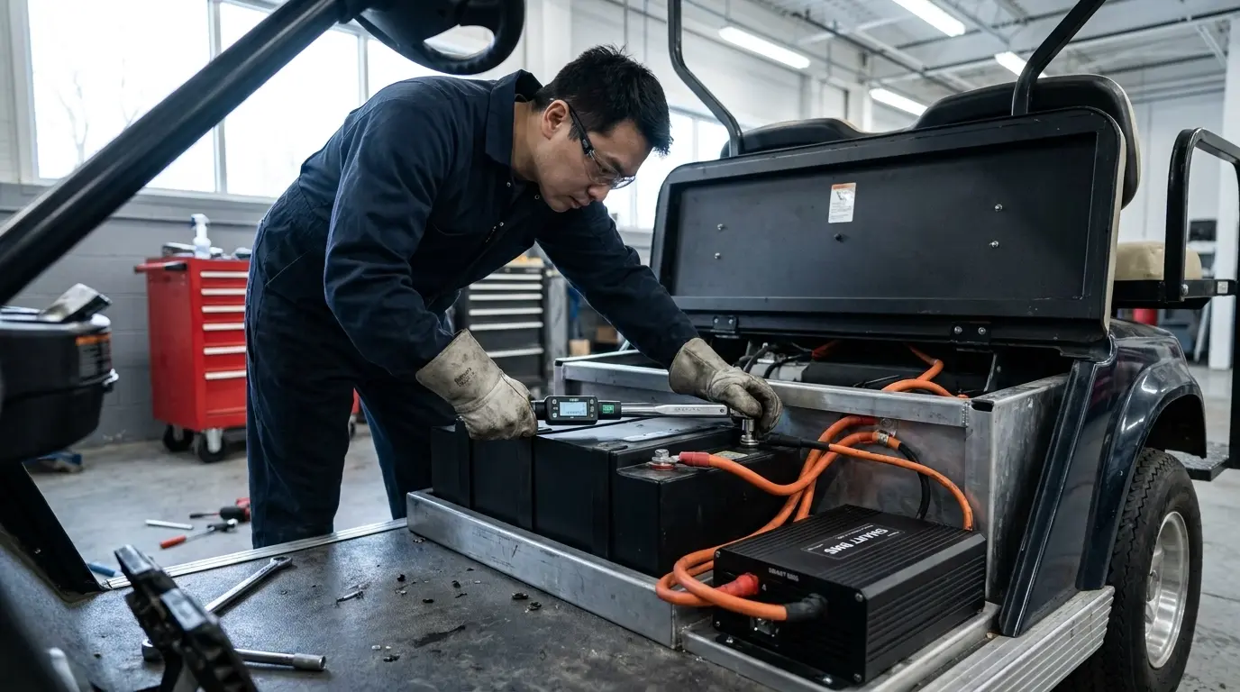
Cable size directly affects BMS health. Undersized wires act like small heating elements. That heat travels into the battery terminals and heats the board’s internal copper traces, causing premature shutdowns.
Searching for High-Current Traction BMS Boards or Complete Packs?
Explore AYAA TECH Product CatalogThermal Sizing in Enclosed Chassis Trays
Internal heat dissipation limits real-world continuous current. Heat generated across the switching array follows Joule’s Law: P = I2 · RDS(on). A 200A current flowing through a 0.8-milliohm MOSFET array generates 32 watts of constant heat.
Silicon resistance climbs as temperatures rise. If junction temperatures rise from 25°C to 100°C, internal resistance can jump by 60%. Conduction losses then increase from 32W to more than 50W at the same amperage. This dynamic can trigger thermal runaway within sealed enclosures.

Engineering Note: Golf cart battery compartments sit under passenger seats without active airflow. Ambient temperatures in these enclosed trays routinely hit 50°C during summer operations. A BMS rated for 200A at 25°C bench conditions must be derated by 25% to 30% for vehicle use.
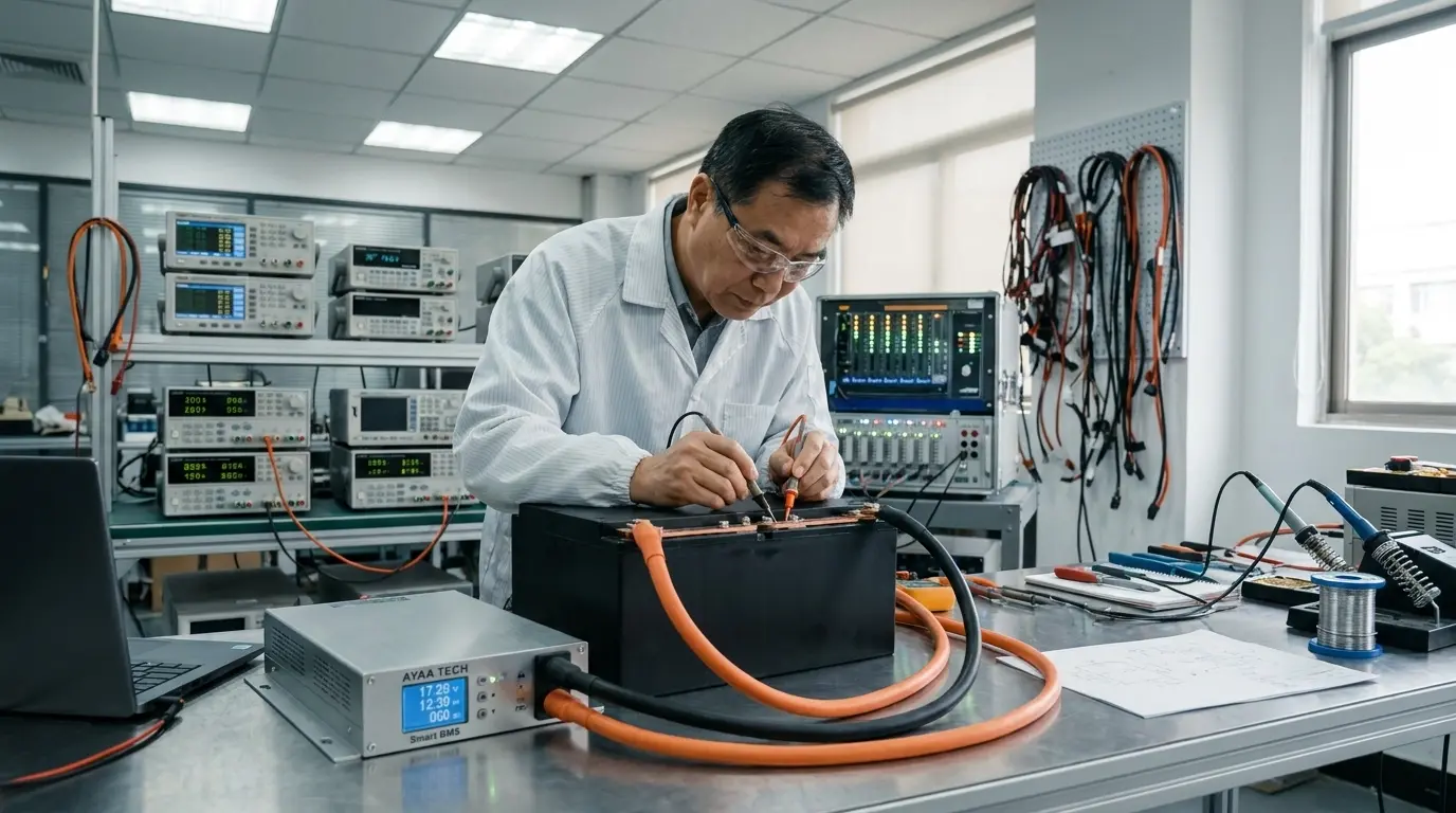
AYAA TECH eliminates these thermal bottlenecks using balanced component placement. Spacing power MOSFETs and copper shunts evenly across the board prevents localized hot spots. The assembly uses industrial thermal silicone pads and conductive gels to route heat outward. Where enclosure volume allows, heavy-gauge aluminum alloy plates or pure copper spreaders transfer heat directly to the chassis to maximize cell cycle life.
Ancillary Electronics: Pre-Charge and Fuel Gauging
Motor controllers contain large input capacitor banks. Connecting an uncharged controller directly to a live pack creates a dead short. Inrush currents routinely exceed 1,000A in the first 500 microseconds.
These massive spikes arc contactors and crack MOSFET dies. A reliable golf cart BMS must integrate an active pre-charge circuit. This circuit routes initial power through a current-limiting resistor. It brings capacitors to 95% of pack voltage before main switches close, preventing hardware damage.

Fuel gauging accuracy is equally vital. LiFePO4 cells maintain an exceptionally flat discharge curve across 80% of their capacity. Voltage readings tell you very little about remaining run time.
True tracking demands shunt-based Coulomb counting. While typical market boards exhibit State of Charge (SOC) drift around 5%, AYAA TECH maintains an algorithm error margin of ≤ 3% across dynamic drive cycles. This precision prevents unexpected shutdowns far from the clubhouse. It also pairs with 1A to 2A bidirectional active balancing, preventing cell drift in high-capacity packs without shedding excess energy as waste heat.
Procurement Audit: Sourcing Traction-Grade Hardware
Procurement teams must look past basic spec sheets. Buying strictly on advertised amps creates expensive warranty claims. Use this checklist during vendor reviews:
- Thermal Rise Data: Demand temperature rise data (ΔT) measured at rated continuous current in an unventilated 45°C testing chamber.
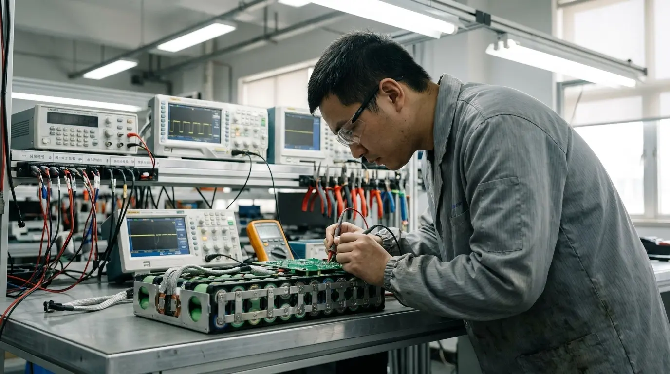
- MOSFET Matching: Confirm the vendor screens parallel MOSFETs for strict RDS(on) and gate threshold (Vth) tolerances to prevent current crowding.
- Safety Certifications: Verify compliance with UL 2271 for vehicle electrical safety, along with UL 1998 or UL 991 for firmware reliability.
- Low-Temperature Protection: Confirm hardware-level low-temperature charge cutoff (LTCP) set at 0°C. This stops dangerous lithium plating while permitting normal discharge.
Correct golf cart bms sizing balances continuous load, surge margins, and heat dissipation. Sizing your system with these factors in mind ensures maximum energy density, long cycle life, and dependable field operation.
Designing a Custom High-Amp Traction Battery Pack?
Consult an AYAA TECH Battery ArchitectTechnical Frequently Asked Questions
Why does my golf cart shut off after three seconds on a hill?
Your motor controller draw is exceeding the BMS Tier 2 overcurrent limit. Steep climbs draw 300A to 450A for several seconds. If your board features an undersized surge window or lacks stepped delays, it treats that normal torque load as a short circuit and isolates the battery.
Can I base my golf cart bms sizing strictly on controller amp ratings?
No. Motor controller ratings usually denote peak AC phase current, not battery DC current. A 400A controller rarely pulls 400A DC from the battery during normal running. Size your BMS using the controller’s maximum continuous and peak DC input ratings found in its engineering manual.
Can a 100A continuous BMS run a standard 48V cart?
A 100A board is too small for practical use. Cruising on flat ground requires only 40A to 60A, but gentle acceleration pulls 120A to 150A. A 100A unit will repeatedly trip during routine acceleration, and constant heat will rapidly degrade internal components.
How does ambient temperature affect BMS sizing?
Battery trays lack forced-air cooling and frequently reach 50°C in summer. Silicon switches generate higher internal resistance as temperatures rise. You must derate a standard 200A board down to 140A–150A continuous in hot, sealed compartments unless it features high-grade heat spreaders.
Why does regenerative braking cause shutdowns on downhill runs?
Downhill runs turn the motor into a generator that pumps high charging current back into the battery. If the pack is fully charged, this surge pushes cell voltages past the Overvoltage Protection (OVP) limit. A common-port architecture combined with CAN bus integration allows the BMS to instruct the controller to taper regen before a hard disconnect occurs.
What happens if my lithium battery lacks a pre-charge circuit?
Connecting an uncharged motor controller directly to a lithium battery causes a 1,000A inrush current spike. This violent surge welds mechanical contactors together and shatters internal MOSFET silicon. Pre-charge circuits eliminate these failures by filling input capacitors gradually.