Top 스마트 BMS Communication Protocols include CAN Bus, RS-485 Modbus, SMBus, I²C, and SPI to manage battery safety, telemetry, and cycle life. A modern Battery Management System (BMS) shares real-time data with external controllers, reporting cell voltages, temperatures, dynamic current limits, State of Charge (SOC), and hardware alarms. These Battery Communication Protocols prevent catastrophic thermal runaway during rapid charging. They also optimize energy delivery for high energy density packs, grid-tied storage, and industrial equipment. Board-level links handle microsecond ADC reads, while system buses manage real-time inverter closed loops and peak shaving telemetry.

Architecture of Smart BMS Communication Protocols
While communication protocols handle real-time data transmission, they operate as part of a broader set of essential Smart BMS features designed for pack safety and control. Battery data flows across three distinct hardware domains. Each level demands specific speed, noise immunity, and cable reach.
Board-Level Telemetry: Chip to MCU
Cell monitoring ICs must stream high-speed analog readings to the host processor. Delays of even a few milliseconds can cause hardware damage during short-circuit events.
- SPI (Serial Peripheral Interface): A 4-wire synchronous bus running over 1 Mbps. It streams raw ADC cell voltages and temperature readings from Analog Front-End (AFE) chips to the main MCU.
- I2C (Inter-Integrated Circuit): A simple 2-wire serial bus running at 100 kHz to 400 kHz. It connects local board devices like EEPROM memory, real-time clocks, and ambient board sensors.
- SMBus (System Management Bus): A customized I2C subset running at 100 kHz. It adds a strict 35 ms timeout to eliminate bus lockups. SMBus uses standard Smart Battery Data (SBData) commands, serving as the benchmark for portable smart batteries.
Subsystem Telemetry: Pack to Host Controller
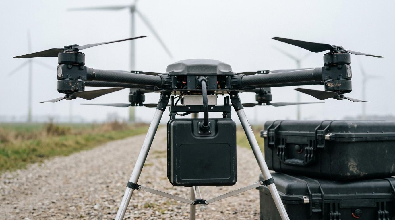
External wiring connects the battery pack to vehicle motor drives, solar inverters, and drone flight computers.
- CAN Bus (CAN 2.0B and CAN FD): The industry standard for mobile systems. It uses differential signaling across two wires. Hardware-level arbitration gives critical safety alerts instant priority over routine telemetry. CAN 2.0B transmits 8-byte payloads, while CAN FD supports up to 64 bytes at 5 Mbps.
- UART (Universal Asynchronous Receiver-Transmitter): A direct point-to-point serial connection. Engineers use UART for diagnostic logging, PC parameter configuration, and Bluetooth Low Energy (BLE) links.
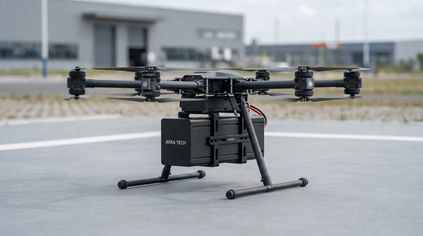
AYAA TECH designs and manufactures everything from bare PCM and standard BMS units to advanced SmartBMS boards and complete Battery Packs. For commercial UAV platforms, AYAA TECH SmartBMS firmware connects natively with open-source flight controllers like PX4 and ArduPilot. This eliminates complex driver programming for hardware integration teams.
Plant-Level Networking: Multi-Rack BESS and Microgrids
Large stationary installations require long wiring runs and centralized master-slave polling.
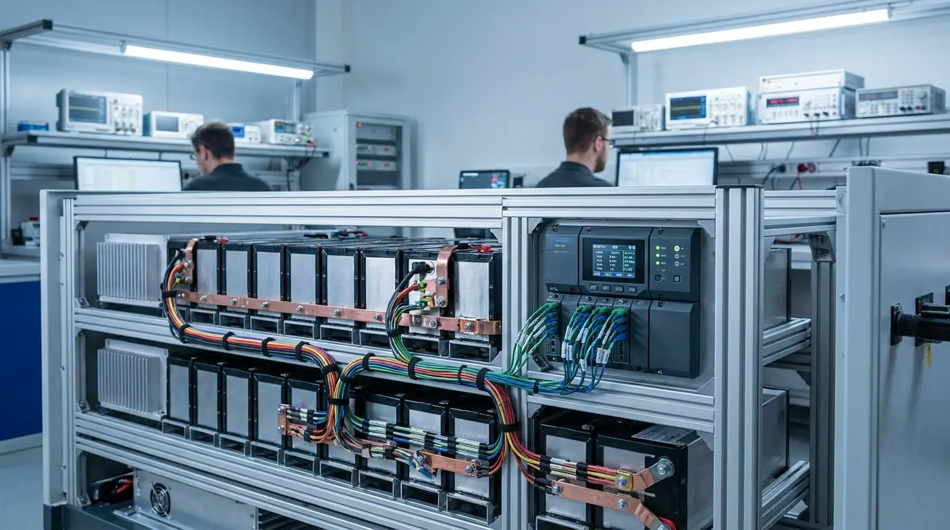
- RS-485 / Modbus RTU: A rugged differential bus that connects up to 32 nodes over 1200 m. It remains the standard for linking multiple rack-level battery units into a central controller.
- Modbus TCP: Modbus protocol frames carried inside standard Ethernet packets. It connects high-voltage battery banks to Energy Management Systems (EMS), SCADA networks, and grid-tied utility controllers.
Technical Comparison of Battery Communication Protocols
Choosing the wrong bus creates electrical noise issues, data bottlenecks, or costly integration delays. Hardware teams evaluate the core performance traits of each protocol below:
| Protocol / Standard | Physical Layer | Max Data Rate | Max Range | Topology | Error Detection | Primary Application |
|---|---|---|---|---|---|---|
| SPI | 4-Wire Single-Ended | > 10 Mbps | < 0.3 m | Single Master / Multi-Slave | None (Optional SW CRC) | AFE to MCU ADC reads |
| I2C | 2-Wire Open-Drain | 400 kbps | < 0.5 m | Multi-Master / Multi-Slave | None | On-board EEPROM, RTC |
| SMBus (v3.2) | 2-Wire Open-Drain | 100 kHz | < 1.0 m | Multi-Master / Multi-Slave | Hardware CRC-8 (PEC) | Smart portable packs, UAVs |
| CAN 2.0B | 2-Wire Differential | 1 Mbps | 40 m | Multi-Master (Arbitration) | 15-bit CRC, Stuff Rule | EV, Robotics, Solar Inverters |
| CAN FD | 2-Wire Differential | 5 Mbps | 40 m | Multi-Master (Arbitration) | Up to 21-bit CRC | Advanced EV, Heavy BESS |
| RS-485 (Modbus) | 2-Wire Differential | 115.2 kbps | 1200 m | Master / Multi-Drop Slave | 16-bit Frame CRC | Commercial BESS, Racks |
| Modbus TCP | 4-Pair Twisted Pair | 100 Mbps | 100 m | Client / Server (Switched) | 32-bit Ethernet Check | BESS to EMS, SCADA, Grid |
This hardware matrix highlights the clear trade-offs between speed, distance, and hardware topology. High-voltage installations require robust differential pairs and certified galvanic isolation barriers.
Closed-Loop Inverter and Charger Control Mechanics
Closed-loop communication lets the BMS actively control the power source in real time. Static charging profiles cause cell imbalance and over-temperature faults.
Dynamic Current and Voltage Throttling
A smart battery continuously updates operational boundaries to protect cell health.
- Charge Current Limit (CCL): The BMS dynamically lowers allowable charge current as cells fill or temperatures drop. This prevents lithium plating in cold environments.
- Discharge Current Limit (DCL): The BMS throttles output current when cells hit low voltage cutoffs or when power stages heat up.
- Charge Voltage Limit (CVL): The BMS sets the exact target voltage, ensuring smooth transitions between charging phases.
Accurate dynamic limits require precise fuel gauging. While standard market options suffer from 5% estimation errors, AYAA TECH maintains an SOC accuracy of ≤ 3%. This precision unlocks maximum usable capacity without false cutoffs.
Inverter Profile Matching and Watchdog Fail-Safes
Most energy storage systems rely on standardized CAN profiles. Established standards include Pylontech CAN, Victron VE.Can, and SMA protocols.
Continuous heartbeat frames ensure active safety. The BMS and external inverter exchange data packets every 1000 ms. If signals stop for more than 3 seconds, the inverter immediately drops current to zero. The BMS then opens its power switches to protect the pack.
Looking for Pre-Integrated Inverter and Flight Controller Power Systems?
Explore AYAA TECH Smart BMS & Battery CatalogCritical Hardware Design Pitfalls and Noise Immunity
Electrical interference and wiring mistakes cause most communication failures in field deployments.
Galvanic Isolation and Ground Loops
High-current switching creates severe ground potential shifts across battery systems.
- Ground Bounce: Connecting non-isolated transceivers across shifting ground references generates destructive circulating currents. These currents burn out transceiver ICs and crash host processors.
- Digital Isolation: Reliable boards deploy 2.5 kVrms digital capacitive isolators and isolated DC-DC converters. This isolates logic circuits completely from high-power return paths.
Engineering Note: Never share logic signal ground (GND) with high-current power ground (B- 또는 P-). Any voltage drop across power shunts will distort logic thresholds, corrupt packets, and destroy silicon.

The RJ45 Pinout Problem
No universal RJ45 pinout standard exists across the battery industry. Mismatched patch cables often route +12 V auxiliary power directly into sensitive CAN or RS-485 data lines. This destroys the communication front-end instantly. Always cross-check pin mappings before applying power.
Engineering Note: Always inspect the physical pinout schematics of both the BMS and host controller before connecting patch cables. Verify that auxiliary power pins never touch differential signal lines.
Line Termination and Bus Load Limits
Differential communication lines require proper impedance matching.
- 120 Ω Termination: Place a 120 Ω resistor at each physical end of the CAN or RS-485 cable. Missing resistors cause signal reflections, ringing, and frame errors.
- Bus Load Capacity: Keep steady-state CAN bus utilization below 50% to 60%. This reserves bandwidth for sudden emergency alarm bursts.
Thermal Layout and Noise Suppression
High current generates intense heat across power MOSFETs and current shunts. Uncontrolled heat alters ADC voltage references and degrades communication transceivers.
AYAA TECH prevents thermal interference by distributing MOSFETs and precision current shunts across balanced copper planes. The hardware incorporates high-grade thermal conductive silicone pads or phase-change gels. For demanding structural designs, custom aluminum alloy or copper heat spreaders extract heat directly. This keeps sensitive communication ICs cool and stable.
Supply Chain and Procurement Risk Management
Procuring battery management hardware requires strict architectural and software evaluation.
Eliminating Proprietary Protocol Lock-In
Proprietary protocols create costly single-source dependencies. They require custom hardware adapters and software drivers. Procurement teams must demand open Modbus register maps and standard CAN .dbc files before signing supplier contracts.
Firmware Version Control and Register Consistency
Unannounced supplier firmware updates can silently break existing system integrations. Small changes to byte endianness, register addresses, or scaling factors crash host controllers. Engineering contracts must mandate strict Engineering Change Notifications (ECN) and guaranteed backward compatibility.

Need Custom Protocols or High-Voltage Pack Engineering?
Consult an AYAA TECH Battery Systems ArchitectFrequently Asked Questions (FAQ)
What is the difference between CAN Bus and RS-485 in battery systems?
CAN Bus uses a multi-master layout with hardware-based message arbitration. It delivers fast, deterministic responses for vehicles and hybrid inverters. RS-485 uses a single-master polling format. It works best for long-distance data collection across multi-rack stationary storage.
Why is closed-loop communication necessary for solar inverters?
Open-loop charging relies solely on gross terminal voltage. Lithium chemistries have flat discharge curves, making voltage-based tracking inaccurate. Closed-loop CAN links stream exact dynamic current limits and cell-level SOC. This prevents overcharging and unnecessary safety cutoffs.
How does SMBus differ from standard I2C?
SMBus runs at a fixed 100 kHz clock and adds a mandatory 35 ms timeout. This timeout prevents stuck bus lines. It also includes hardware CRC error checking and standardized Smart Battery Data commands.
What happens when a BMS loses communication with an external charger?
The system triggers a communication timeout fault. The charger drops current output to 0 A within 1 to 3 seconds. If the link stays offline, the BMS opens its safety switches to block unmonitored power flow.
Why do high-voltage battery arrays require galvanic isolation?
High-voltage switching induces heavy voltage spikes across ground planes. Without galvanic isolation, ground loop currents flow through communication lines. This burns out transceivers and introduces severe electrical shock hazards.
How do technicians fix RJ45 pinout mismatches?
Technicians map pin assignments between the battery and host controller before installation. They deploy custom crossover cables or configurable adapter boards. This aligns differential lines correctly while isolating unused power pins.
What is the safe CAN bus load limit for multi-pack systems?
Maintain steady-state CAN bus utilization between 50% and 60%. This headroom ensures that high-priority emergency fault frames transmit immediately without queuing delays.
Resolving Field Bus Errors or Pinout Conflicts?
Contact AYAA TECH Engineering SupportReferences
- ISO 11898-1 / ISO 11898-2: Road vehicles — Controller area network (CAN) physical and data link layers.
- CiA 454 (EnergyBus): Application profile for energy management systems in light electric vehicles.
- SBS Implementers Forum: System Management Bus (SMBus) Specification v3.2 and SBData v1.1.
- Modbus Organization: Modbus Application Protocol Specification V1.1b3.
- IEC 62619: Safety requirements for secondary lithium cells and batteries in industrial applications.
- SunSpec Alliance: Energy Storage Model Specifications for DER Integration.