- Industries

Home Backup & Garden BMS
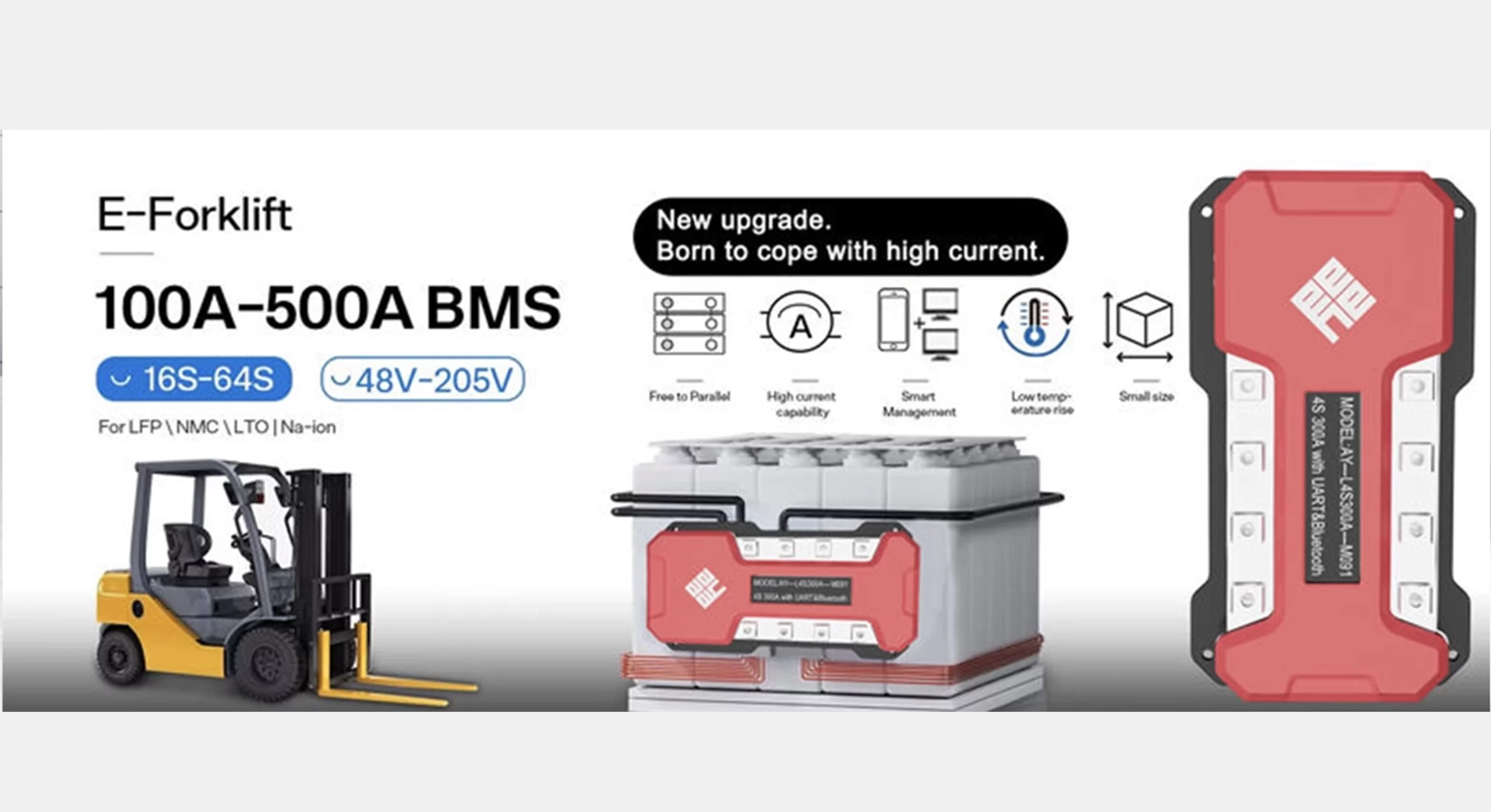
View More >Electric Forklift BMS
View More >Golf Cart BMS
View More >Electric Two-wheeler BMS
View More >Aviation & UAV BMS
View More >BMS For Power Tools
View More >Medical Equipment BMS
View More >


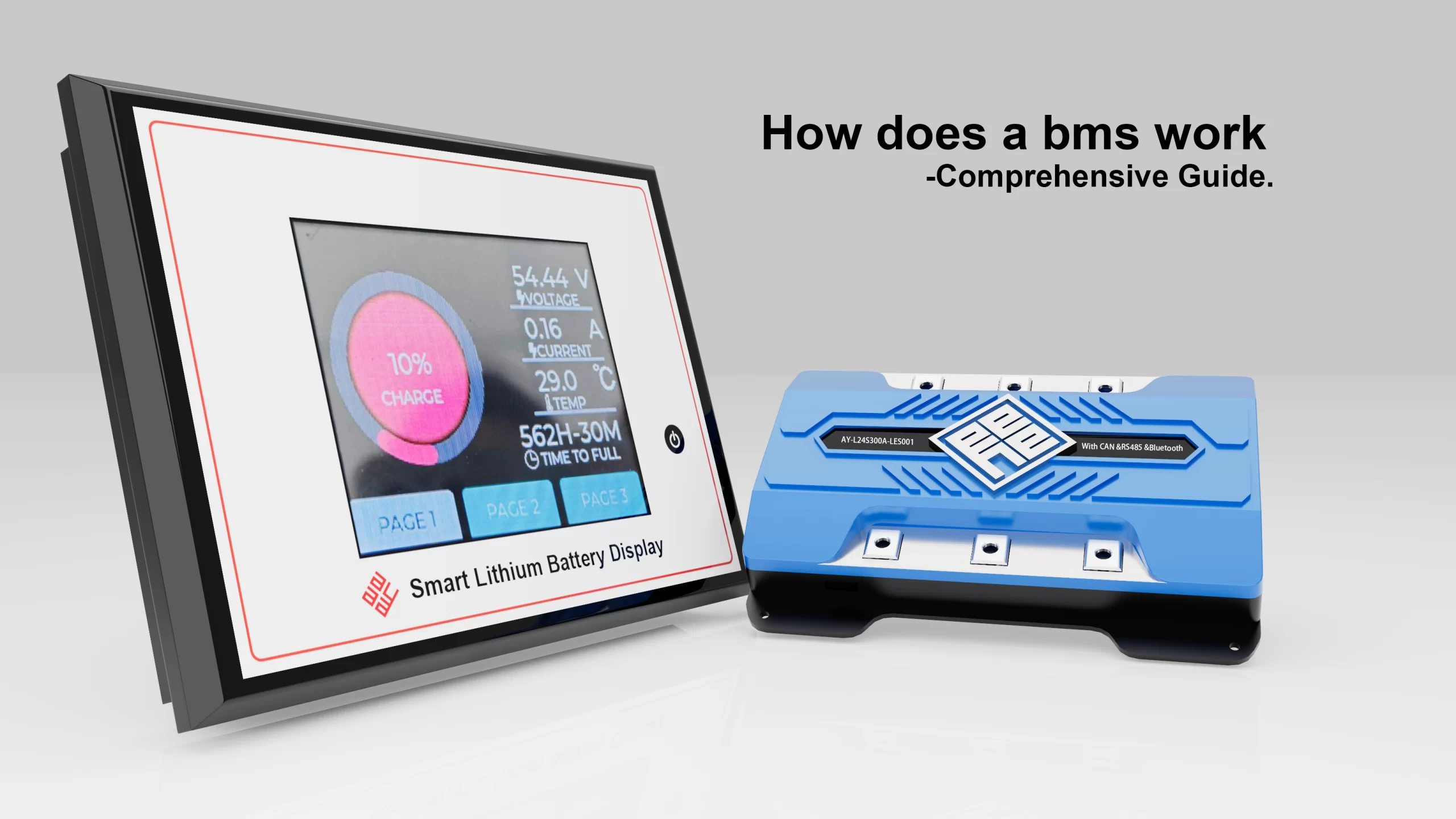
Home About Us EVENTS & NEWS Why Does a BMS Wiring Diagram Matter for Battery Performance?
Battery packs are used for much more than just storing power in the current electrification environment, which includes drones, medical power systems, electric forklifts, energy storage, and EVs.
They are living electrochemical systems that need to be regulated, watched after, and safeguarded.
The Battery Management System (BMS) is the focal point of that intelligence.
However, one crucial but frequently disregarded factor impacts whether a pack succeeds or fails.
Even while developers concentrate on firmware, balancing algorithms, and communication protocols: The BMS wiring diagram.
A bms wiring diagram is more than just a technical schematic.
Voltage detection, current channels, balancing signals, MOSFET control, temperature monitoring, communication nodes, grounding strategy, and system redundancy are all specified in this blueprint.
Even the most sophisticated BMS can malfunction without the proper schematic, leading to heat accumulation, imbalance-related aging, short circuits, or even thermal runaway.

A schematic drawing that illustrates how each battery cell is connected to the BMS control board is called a BMS wiring diagram.
It makes clear:
Series cell taps (S1–S16 etc.)
Balance wires
Power MOSFET charge/discharge paths
Temperature sensor placement
CANBUS / SMBUS / UART ports
Ground reference and isolation points
The cells in a battery are similar to the muscles in a human body, but the brain is represented by the BMS.
The nervous system map that directs signals throughout the body is represented by the BMS wiring diagram.
Assembly teams make guesses in the absence of this map.
Guessing also equates to failure in batteries.
When engineers discuss BMS systems, balancing—maintaining equal cell voltages to avoid weak-cell aging—often comes to mind first.
However, balancing is only possible if cell groups are properly connected by the wiring.
The BMS may identify inaccurate readings if the wire harness reads the incorrect voltage tap. Example:
| Wiring Error | BMS Response |
|---|---|
| Mis-tapped S6 reads as S7 | BMS triggers false high-voltage alarm |
| Temperature sensor wired to wrong group | Cooling never activates |
| Parallel groups mis-mapped | Balancing burns energy where it’s not needed |
A BMS wiring diagram guarantees that every tap is associated with the appropriate cell group.
This accuracy is even more important in packs like the bms wiring diagram for lithium ion battery systems (such as 14S 52V or 16S 48V), as even a 10-mV balancing error can result in a 10–15% useable cycle loss over 1,000 cycles.
Balancing is a function that must be precisely managed, and wiring is the first step in this process.
The most important aspect of wiring is safety.
Because lithium-based chemistry has the largest energy density, errors are most likely to occur.
A lithium battery’s bms wiring diagram describes:
Where current flows during charge and discharge
How the BMS disconnects power during over-voltage, low-voltage, short-circuit, or overheating
Placement of dual redundant sensors for high-power packs
Whether a fuse is on the positive or negative rail
Consider two wiring scenarios:
A short circuit could completely avoid the BMS if the discharge MOSFET circuit is wired incorrectly, increasing the danger of thermal runaway.
The BMS might not identify overheating until harm has been done if a temperature sensor is placed too far away from high-stress cells.
These blind spots are removed with a professionally created BMS wiring diagram.
It guarantees that rather than just sitting inside the battery pack, the BMS can see and manage it.
Yes—deeply. Unbalanced voltages caused by improper wiring promote aging.
However, energy efficiency also affects lifetime.
A bms wiring diagram for lithium ion battery directly affects:
Charge cut-off precision
Passive / active balancing effectiveness
Standby current loss
Voltage drop across sensing lines
Heating rises, balancing takes longer, and usable Wh output decreases if high-resistance wiring adds even 50 mΩ more impedance to a sensing line.
Without replacing any cells, wiring quality alone can increase the usable lifespan of long-term storage applications (such as solar ESS and telecom backup) from four to eight years.
Because standardization is essential to production consistency.
The BMS wiring diagram is a QC delivery tool for mass-production packs, such as electric golf carts, forklifts, scooters, and drones:
| Stage | Dependency |
|---|---|
| Cell Assembly | Requires wiring route |
| Spot-Welding Map | Depends on diagram sequence |
| FPC or Harness Procurement | Driven by wiring diagram |
| BMS Software Calibration | Needs correct tap order |
Every downstream examination is unsuccessful if a technician uses the incorrect reference location when welding nickel plates.
Training, quality control, replacement procedures, and post-purchase troubleshooting become scalable once the wiring diagram is secured and verified.
Real cases show predictable failures:
The pack charges only to 70% capacity
Power-off occurs under high load (false over-current)
Balancing never completes
One cell reaches 4.35V while the rest are 4.1V (dangerous)
Battery explodes after a short-circuit bypass
99% of these failures happened before assembly—at the diagram stage.
A BMS wiring diagram is not documentation.
It makes the difference between anarchy and a scalable power company.
Yes—chemistry matters.
Lithium ion batteries have a different bms wiring diagram than LiFePO4 and polymer systems because:
| Chemistry | Voltage Range | Wiring Sensitivity | Notes |
|---|---|---|---|
| Lithium-Ion (NCM/NCA) | 3.0–4.2V | Extremely sensitive | Balancing required |
| LiFePO4 | 2.5–3.65V | Thermal stable | Requires accurate temp mapping |
| Solid-State | Varies | High energy density | Must integrate thermal plates |
In EV-grade packs, wiring includes:
Dual temperature sensors per module
CANBUS redundancy
Active balancing boards
Contactors + precharge resistors
There isn’t a universal diagram. A distinct wiring structure is necessary for each chemical.

Yes. Application defines wiring strategy.
| Application | Wiring Priorities |
|---|---|
| Drone battery | Ultra-low weight harness |
| Forklift | High-amp MOSFET layout |
| Energy Storage System | Redundant temperature loops |
| Medical Device Battery | Fail-safe disconnection design |
| eBike Battery | Anti-vibration FPC wiring |
Before choosing a diagram, engineers should ask:
What is maximum discharge current?
Will the pack operate in vibration or humidity?
Must the BMS communicate via CAN or UART?
Does the market require UL / UN38.3 certification?
Field technicians don’t have time to speculate.
A printed lithium battery BMS wiring diagram allows service personnel to quickly:
Identify failed cells
Verify B-/C-/P- terminals
Replace harnesses
Diagnose MOSFET failure
Test NTC sensor operation
In commercial fleets, fast troubleshooting = lower TCO (Total Cost of Ownership).
One consistent factor causes battery brands to fail: inconsistent quality.
Additionally, unregulated wiring procedures are the root cause of inconsistency.
Results occur when a business standardizes its BMS wiring diagram across all product lines:
Scalable production
Reduced warranty claims
Faster certification
Lower training cost
Stronger customer trust
Wiring diagrams safeguard margin and reputation in a market where the lowest bidder frequently prevails.
A battery without a BMS is dangerous.
A battery with a BMS—but no wiring diagram—is unreliable.
A battery with both is a commercial product capable of scale.
Remember this when designing an EV system, medical device battery, drone powertrain, forklift pack, or solar ESS:
All smart battery innovation begins with a smart wiring diagram.
Ayaa Technology offers comprehensive battery management solutions for international performance-driven markets for companies looking for engineering BMS solutions, including design, wiring diagram development, BMS production, communication integration, validation, and testing.
Q1:How to connect BMS to batteries?
A1:1.Choose the Configuration of Your Battery Pack.
2.Get the battery cells ready.
3.Use nickel strips to join the cells.
4.Set up the BMS Module.
5.Protect Every Connection.
6.Check the battery pack.
7.Last Assembly.
8.Put on a shrink wrap.
Q2:What is BMS in electrical?
A2:Battery Management System, or BMS for short, is the “brain” of rechargeable batteries in electrical systems.
Q3:How to connect to BMS system?
A3:The BMS and water heater should be linked to the BMS Interface as follows:
Attach the power supply cord to the BMS Interface’s upper-right connection.
Use a double-pole isolator to connect the cable’s opposite end to the main power source.
Q4:What is 1S, 2S, and 3S in BMS?
A4:The S stands for series cells, which might be a single cell or several in tandem.
Voltage is increased (additively) when cells are connected in series.
For instance, 1S = 3.7V, 2S = 7.4V, 3S = 11.1V, and so on are nominal voltages.
Your battery pack’s series cell count and, consequently, voltage must be matched by a BMS.
Q5:What is the 80 20 rule for batteries?
A5:The “Goldilocks zone” for battery health is the 80/20 rule, which suggests that lithium-ion batteries (phones, EVs, etc.) be kept between 80% (don’t overcharge daily) and 20% (don’t fully discharge) to greatly extend their lifespan by reducing stress.
Tesla suggests 80% for daily use and avoiding deep discharges below 20% for longevity.
Batteries survive longer before needing to be replaced since this reduces degradation, even though it lowers immediate capacity (you receive 60% useable range).
Contact Us