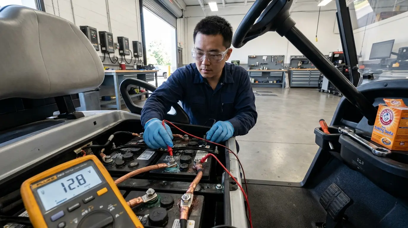
A forklift battery management system (forklift BMS) is an electronic controller that protects the pack. It measures cell voltage, pack current, and operating temperature. It protects the pack from overcurrent, overvoltage, undervoltage, and extreme heat. The system also balances individual cells and communicates over the CAN bus.
Its primary duty is maintaining battery safety and operational reliability. It calculates accurate state of charge for dashboard display. It also directs industrial chargers to deliver optimal current during fast charging. Choosing the right unit requires matching truck voltage, continuous current, pre-charge safety, and CAN protocols.
For warehouses, the BMS makes lithium conversion practical. It eliminates dedicated battery rooms, water top-ups, and mid-shift battery swaps. Trucks can opportunity-charge during brief 15–30 minute breaks and return straight to work.
A weak BMS causes most industrial battery failures. Contactors weld shut, trucks lose braking power on ramps, or cells freeze. This complete guide explains how a forklift BMS functions and how to select the best model.

Understanding the Two Different Types of Forklift Battery Management Systems
Onboard Electronic Control Units vs. Facility-Wide Fleet Management
Searching for “forklift BMS” often returns two completely different systems. People in the material handling industry frequently confuse them.
The first type is a facility-level fleet management system. This is warehouse software tied to older lead-acid fleets. It tracks which battery sits in which truck and logs watering schedules. It treats batteries as inventory assets and never interacts with individual cells.
The second type is the onboard lithium forklift BMS. This is physical hardware and firmware mounted inside the battery pack. It measures cell voltages, switches main power contactors, and talks to the truck controller. This guide focuses entirely on this onboard electronic system.
The two systems are not rivals. Some operations use both together. The onboard BMS sends live pack data directly to the facility dashboard. However, when purchasing a lithium battery, you are buying an onboard unit.
How Lithium-Ion BMS Hardware Eliminates the Traditional Battery Room
Lead-acid forklift batteries demand massive facility overhead. Warehouses need dedicated charging rooms, hydrogen ventilation, eyewash stations, and acid-resistant flooring. Crews must perform hazardous watering and weekly equalization charges. Multi-shift operations also require two or three heavy batteries per truck.
A lithium iron phosphate (LFP) pack with an onboard BMS eliminates these burdens. LFP batteries do not off-gas toxic fumes, so special ventilation is unnecessary. They eliminate watering and prevent acid spill risks.
LFP packs also tolerate partial charging without suffering lead-acid sulfation. The BMS regulates high charge currents safely. Trucks simply plug in at the dock during scheduled breaks. As a result, fleets run around the clock with only one battery per truck.
Core Functions of an Industrial Forklift Battery Management System
Cell Monitoring and High-Precision State of Charge Tracking
The forklift BMS reads every cell group continuously. Quality units sample cell voltage within ±25 mV. They track total pack current using a precision shunt or Hall-effect sensor. The BMS uses these metrics to compute state of charge (SOC).
Calculating SOC on an LFP battery is exceptionally difficult. The voltage discharge curve remains flat across most operating ranges. As a result, voltage alone cannot determine remaining battery capacity.
A dependable BMS combines coulomb counting with open-circuit voltage corrections. It also compensates for operating temperature. Cold cells deliver less usable energy under load. A simple gauge that ignores temperature drops from 40% to zero without warning.
At AYAA TECH, our SOC algorithm accounts for ambient thermal shifts. It keeps estimation error at 5% or less. Drivers can trust the dashboard gauge when deciding whether to move another pallet.
Active Balancing vs. Passive Balancing Under Heavy Duty Cycles
Cells in a series string never remain perfectly identical. Over time, cell capacities drift apart. The weakest cell always limits total pack runtime. Balancing corrects this natural cell divergence.
Passive balancing burns excess energy from high cells as heat through resistors. It operates at low currents, typically 50–100 mA. Active balancing shifts energy from stronger cells to weaker ones at 1 A–5 A.
This distinction matters immensely during heavy forklift operations. Passive balancing requires long, slow charges at high voltages to balance cells. Busy warehouses that opportunity-charge for 20 minutes provide almost no balancing window. Cell imbalance grows, usable capacity shrinks, and the truck cuts out early.
Active balancing adds circuit complexity and increases initial hardware costs. For single-shift trucks charging overnight, passive balancing works fine. For multi-shift fleets using opportunity charging, active balancing is mandatory to prevent premature capacity loss.
| Merkmal | Passive Balancing | Active Balancing |
|---|---|---|
| Typical balancing current | 50–100 mA | 1 A–5 A |
| Operating mechanism | Burns excess energy as heat | Transfers energy between cells |
| Effectiveness during short break charges | Minimal | Hoch |
| Board complexity and cost | Lower | Higher |
| Recommended duty cycle | Single shift with overnight charging | 24/7 multi-shift with opportunity charging |
Multi-Point Thermal Regulation and Low-Temperature Preheating
Thermal sensors placed throughout the pack identify dangerous hot spots and cold zones. The BMS uses these temperature readings to throttle current or halt operations.
High current draw generates substantial thermal stress inside industrial units. Power MOSFETs and current-sense shunts carry heavy continuous loads. These components act as primary heat sources on the circuit board.
AYAA TECH spaces heat-generating components evenly across the board layout. We use premium thermal silicone gap pads to transfer heat into aluminum spreaders. This layout prevents localized hot spots and preserves measurement accuracy during heavy lifting.
Sub-zero operating environments present different engineering challenges. Freezing conditions require dedicated heating controls, detailed in the cold-storage section below.
Critical Engineering Safeguards Often Overlooked in Forklift Applications
Standard BMS articles focus only on basic overvoltage and overcurrent protections. Industrial forklifts present far tougher electrical demands. The following four engineering challenges cause most field breakdowns.
Managing Regenerative Braking Spikes During Heavy Ramping
Loaded forklifts driving down steep warehouse ramps generate significant regenerative braking energy. The traction motor acts as a generator, pushing massive current back toward the battery. This surge causes pack bus voltage to spike abruptly.
A basic BMS treats this voltage surge as an ordinary overcharge event. It trips overvoltage protection and instantly disconnects the battery. On a forklift, sudden power disconnects are dangerous. The truck can lose electrical braking and power steering on a ramp.
An industrial forklift BMS must identify regenerative current pulses dynamically. It communicates with the vehicle controller to absorb energy smoothly. When necessary, it routes excess voltage into external braking resistors instead of shutting down.
Pre-Charge Circuits to Prevent Contactor Welding from Inrush Current
Forklift motor controllers contain massive capacitor banks across their DC input terminals. These capacitors often total several thousand microfarads. When first connected, an empty capacitor behaves like a dead short circuit.
Connecting the battery without current limiting creates a massive inrush surge. This current spike arcs across contactor tips and frequently welds them shut. A welded contactor prevents the BMS from disconnecting power during emergencies. The surge can also destroy solid-state MOSFET switches instantly.
A proper pre-charge circuit prevents this catastrophic failure mode. It routes initial current through a current-limiting resistor and auxiliary relay. This path charges the motor capacitors to 90% of pack voltage before the main contactor closes.
Never bypass pre-charge circuitry to cut manufacturing costs.

Multi-CAN Architecture for Seamless Integration with OEM Forklifts
A forklift’s communication network carries heavy data traffic. Combining the truck controller, battery charger, and telematics gateway onto one bus creates data collisions. Quality industrial systems isolate these streams across three physical CAN-bus channels:
- Port 1: Vehicle Bus. Communicates with the truck controller and dash display via SAE J1939 or CANopen. It handles proprietary protocols for Linde, Toyota, Hyster, and Yale trucks.
- Port 2: Charger Bus. Directs the industrial charger to deliver optimal voltage and current based on real-time cell parameters.
- Port 3: Telematics Bus. Streams operational diagnostics to cloud gateways without injecting noise into the primary drive network.
Modern trucks enter safe-mode lockout if the battery fails to reply correctly. Resolving proprietary communication handshakes is critical for successful retrofits.
Conformal Coating and Sealing Against Cold-Storage Condensation
Cold-chain forklifts move between -30°C freezer vaults and humid loading docks continuously. Rapid temperature swings create heavy condensation inside battery enclosures. Moisture on energized circuit boards leads to dendritic corrosion, leakage paths, and signal errors.
Reliable cold-storage electronics require heavy conformal coating. Protective battery enclosures must meet stringent IP65 or IP67 ingress standards.
Charging frozen cells causes lithium ions to form metallic dendrites on anodes. This permanent plating degrades capacity and triggers internal cell short circuits. A qualified BMS locks out charging below freezing automatically. It activates internal PTC heating pads, warming cells above 0°C before permitting charge current.
Charging frozen lithium batteries at any rate causes irreversible damage.
Choosing an industrial BMS for your forklift fleet?
Explore Product CatalogKey Technical Specifications for Selecting the Right Forklift BMS
Matching Voltage Classes, Cell Series Configurations, and Continuous Amps
Forklift categories determine system voltage, series cell counts, and continuous current ratings. The reference table below outlines standard industrial LFP configurations.
| Truck Class | Typical Vehicle Type | Nominal Voltage | LFP Series Config | Typical Continuous Current | Balancing Suggestion |
|---|---|---|---|---|---|
| Class 3 | Pallet jacks, walkie stackers | 24V | 8S | 150A–200A | Passive for light duty; active for multi-shift |
| Class 2 | Reach trucks, order pickers | 36V / 48V | 12S / 16S | 200A–300A | Active recommended |
| Class 1 | Counterbalance rider trucks | 48V / 80V | 16S / 24S–32S | 300A–500A | Active strongly recommended |
Hydraulic lift pumps draw heavy current spikes. Lifting rated capacity draws two to three times continuous current for several seconds. The BMS current shunt and trip thresholds must handle these surges without nuisance trips.
Solid-State MOSFET Switching vs. Heavy-Duty Contactor Relays

Industrial battery management systems disconnect high-current DC power using two primary switching technologies:
MOSFET switching mounts parallel solid-state transistors directly on the circuit board. This architecture is compact, silent, fast, and eliminates moving parts. However, high continuous current creates substantial resistive heat dissipation. Solid-state switching best suits compact Class 3 pallet jacks.
DC contactors use hermetically sealed ceramic relays. They handle high voltages and heavy inductive loads with negligible resistance. They provide true galvanic air-gap isolation when opened. Trade-offs include larger physical dimensions, continuous coil power draw, and mandatory pre-charge circuits.
Never specify solid-state MOSFET boards for heavy-duty 80V counterbalance trucks. Thermal loads and short-circuit failure risks on MOSFET banks are unacceptably high. Heavy trucks demand rugged DC contactors.
| Selection Factor | Solid-State MOSFET Switching | Heavy-Duty DC Contactor |
|---|---|---|
| Optimal voltage range | Low voltage (24V–48V) | High voltage (48V–80V+) |
| Physical footprint and weight | Highly compact and lightweight | Larger enclosure required |
| Thermal losses at peak load | High thermal generation | Negligible contact resistance |
| Pre-charge circuit requirement | Empfohlen | Mandatory |
| Primary failure mode | Shorted transistor junction | Contact pitting or welding |
Correct thermal engineering remains vital regardless of switching architecture. Proper component spacing and heat spreaders protect all sensitive control circuits.
Mandatory Safety Certifications and Compliance Standards
Commercial forklift battery conversions must comply with established industrial safety regulations:
- UL 2580: Standard for batteries used in electric energy storage and industrial trucks.
- UL 991 / UL 1998 / IEC 61508: Evaluates functional safety, firmware reliability, and hardware failure modes.
- ISO 13849: Validates safety-related machinery control architectures up to Performance Level d (PLd).
Always demand official testing laboratory certificates from prospective suppliers. Verify that testing applies to the complete system rather than isolated secondary components.
Real-World Operational and Financial Benefits for Warehouse Fleets
True Opportunity Charging Without Battery Degradation
Lead-acid batteries suffer severe capacity loss if charged in short, incomplete bursts. In contrast, LFP cells managed by intelligent BMS algorithms thrive on opportunity charging.
The BMS regulates charge intake dynamically based on real-time cell temperatures and voltages. Operators plug in during scheduled breaks, keeping equipment running across consecutive shifts. Eliminating spare batteries and swap equipment lowers total cost of ownership substantially.
Predictive Maintenance Through Cloud-Connected Telematics
Modern forklift BMS units broadcast performance diagnostics through dedicated telematics ports. Cloud platforms track cell voltage deviations, temperature profiles, and total lifetime amp-hour throughput.
Maintenance managers receive automated alerts before minor cell variances cause unexpected roadside failures. This visibility converts costly emergency repairs into planned maintenance.
Need a custom BMS engineered for proprietary forklift protocols?
Request a Custom BMS SolutionFAQ
1. What is the difference between a forklift BMS and a battery monitoring system?
A battery monitor observes and records data passively. It displays voltage, current, and temperature on an external screen. In contrast, an active forklift BMS has the authority to switch circuits. It balances cells, throttles current, directs chargers, and isolates power during faults.
2. How does a forklift BMS protect the battery during rapid opportunity charging?
The BMS monitors cell voltages and temperatures continuously during charging sessions. It commands the industrial charger via CAN bus to deliver optimal current. If any cell approaches maximum voltage or overheats, the BMS lowers charge current instantly.
3. Why does a forklift shut down and display a BMS error code?
Common fault triggers include sudden lift overcurrent, low cell voltage, overheating, communication loss, or pre-charge timeouts. A truck that trips only during heavy lifts indicates that current limits are set too low. Consult the manufacturer’s fault codes to identify the exact cause.
4. Can I retrofit a generic lithium BMS onto an older electric forklift?
Retrofitting generic units requires caution. Off-the-shelf boards often lack peak lift current capacity, regenerative braking absorption, or proper CAN integration. Always verify continuous amperage, pre-charge support, and vehicle protocol compatibility before attempting a conversion.
5. How does temperature affect forklift BMS operation in cold storage facilities?
Sub-zero temperatures reduce usable capacity and increase internal cell resistance. Charging frozen cells causes irreversible metallic lithium plating. A specialized cold-chain BMS halts charging below freezing, activates internal heaters, and permits current only after cells warm up.
6. What is the difference between active and passive balancing on an industrial forklift?
Passive balancing drains higher cells through small resistors at 50–100 mA. Active balancing shuttles energy between cells at 1 A–5 A. For multi-shift trucks that charge in brief 20-minute sessions, active balancing is necessary to keep cells balanced.
7. What communication protocols are most commonly used in forklift battery management?
Industrial material handling equipment relies predominantly on CAN-bus networks. SAE J1939 and CANopen serve as primary baseline standards. Many forklift manufacturers incorporate proprietary message formats, requiring custom software translation.