










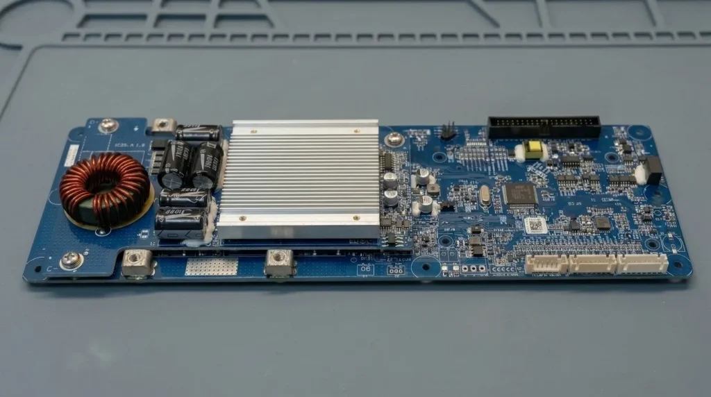
A BMS overcharge and overdischarge protection circuit prevents battery failure by monitoring individual cell voltages and disconnecting power circuits at defined safe limits. Overcharge protection isolates the charger before high voltage triggers electrolyte oxidation or thermal runaway. Overdischarge protection cuts off the load before deep discharge causes permanent copper dendrite dissolution and cathode damage. Beyond basic cutoffs, high-reliability battery packs leverage advanced Smart BMS features—including high-precision cell monitoring, dynamic hysteresis control, and ultra-low quiescent current—to ensure long-term stability.
How BMS Overcharge and Overdischarge Protection Works in Practice
Single-Cell Sensing vs. Pack-Level Voltages
Pack-level voltage readings lie. A 16S LiFePO4 battery pack reading 51.2 V might seem perfectly healthy. Yet, one weak cell string could sit at a hazardous 3.80 V while others remain at 3.16 V.
ال Analog Front-End (AFE) IC must sample every single series string directly. Fast sampling rates above 10 Hz keep energy density high while preventing localized voltage spikes.
Voltage drift also ruins State of Charge (SOC) tracking. Most standard boards show 5% SOC calculation error. AYAA TECH SmartBMS units keep SOC estimation error under ≤ 3%. This accuracy prevents false cutoff triggers during long discharge cycles.
MOSFET Cutoffs and Thermal Management
When voltage exceeds safe limits, gate drivers open solid-state N-channel MOSFETs. This action stops charge current within milliseconds. It halts electrolyte oxidation and metallic lithium plating instantly.
Engineering Note: Operating switching MOSFETs near their junction temperature limits (Tj) accelerates driver failure. High heat increases internal resistance (RDS(on)), causing board overheating. AYAA TECH arranges MOSFETs and current-sensing resistors across optimal thermal zones. We use high-grade thermal conductive silicone pads with aluminum or copper heat sinks to dissipate heavy heat loads efficiently.
Low-Voltage Cutoffs and System Recovery
Threshold Limits and Dynamic Voltage Sag
Deep discharge damages internal battery structures. LiFePO4 cells need a hard cutoff at 2.50 V. NMC cells require disconnection at 2.70 V. Dropping lower dissolves copper current collectors into liquid electrolyte.
Heavy discharge loads complicate low-voltage detection. High current draw creates internal resistance drops (I × R). This voltage sag causes premature protection trips even when the battery holds 30% capacity.

UAVs and mobile robotics suffer from this issue during acceleration. AYAA TECH SmartBMS systems integrate natively with all major open-source flight control systems. This integration filters transient voltage sags, preventing unexpected power cutoffs during sudden throttle bursts.
Hysteresis Voltage and Circuit Chattering
Removing a heavy load causes cell voltage to bounce back instantly. This rebound causes circuit chattering.
Without hysteresis, a battery cutting off at 2.50 V quickly recovers to 2.70 V. The system re-engages the load, collapses the voltage, and shuts off again. This rapid switching destroys relays and MOSFETs.
A robust BMS overcharge and overdischarge protection circuit enforces a distinct release voltage (VUVR). The battery stays disconnected until a charger raises cell voltage above 2.80 V – 3.00 V.
Engineering Hazards in Energy Storage Systems
Quiescent Current and Battery Storage Failure
BMS protection boards draw power even after cutting off loads. High quiescent current (Iq) drains battery packs during long warehouse storage.
Engineering Note: Cell voltage staying below 1.50 V forces copper into solution. Recharging later grows copper dendrites through the separator. This causes direct internal short circuits and fires. High-reliability systems must enter deep sleep mode with Iq < 2 µA post-cutoff.
Inductive Voltage Spikes and Inrush Current
Motor loads create severe voltage spikes (L × di/dt) during emergency cutoffs. These spikes destroy switching transistors instantly.
Engineers must add Transient Voltage Suppressor (TVS) diodes and parallel RC snubber circuits. These components absorb inductive kickback across the MOSFET array.
Cell Imbalance and Reduced Cycle Life
Cell capacities diverge over time. A single weak string reaching low voltage forces the entire battery pack to shut down early.
Active balancing fixes this issue during charge cycles. Keeping cells balanced maximizes usable energy density and extends overall cycle life in peak shaving and grid-tied storage systems.
Need Industrial-Grade Protection for Your Battery Assemblies?
Explore AYAA TECH Product CatalogBMS Electrical Specifications Reference

Selecting a BMS requires matching electrical thresholds directly to cell manufacturer specifications. The parameter matrix below details core operating limits across standard lithium chemistries.
| Electrical Parameter | LiFePO4 Specification | NMC / Li-ion Specification | Design & Sourcing Impact |
|---|---|---|---|
| Overcharge Cutoff (VOVP) | 3.65 V ± 0.025 V | 4.25 V ± 0.025 V | Prevents cathode lattice damage and gas creation. |
| Overcharge Release (VOVR) | 3.45 V – 3.50 V | 4.05 V – 4.15 V | Defines automatic charge restoration threshold. |
| Overdischarge Cutoff (VUVP) | 2.50 V ± 0.05 V | 2.70 V – 2.80 V ± 0.05 V | Prevents permanent copper current collector dissolution. |
| Overdischarge Release (VUVR) | 2.80 V – 3.00 V | 3.00 V – 3.20 V | Stops load chattering by requiring voltage recovery. |
| Protection Delay (tdelay) | 100 ms – 1000 ms | 100 ms – 1000 ms | Filters out temporary voltage drops from motor startup pulses. |
| Quiescent Current (Iq) | < 2 µA (Sleep Mode) | < 2 µA (Sleep Mode) | Controls shelf-life duration after triggering deep-discharge protection. |
Setting these exact parameter boundaries protects long-term battery cycle life. It also ensures full access to usable energy storage capacity during normal operation.
Facing Unsolved Voltage Sag or Form-Factor Constraints?
Consult a Battery ArchitectTechnical FAQ
How do you wake up a BMS locked in overdischarge protection mode?
Apply an external charging voltage across the power terminals (P+ and P-). The charging potential must exceed the current open-circuit pack voltage. This potential activates the AFE IC, turning the discharge MOSFET back on. Advanced units use 0V-charge circuits to safely trickle-charge deeply depleted cells.
Can a lithium battery recover after overcharging?
Mild overcharging caught immediately causes minor capacity loss. You must discharge the pack under strict thermal controls. However, if overcharging causes cell swelling, venting, or temperatures above 80°C, internal mechanical damage is permanent. You must safely decommission the battery.
What is the difference between overcurrent protection and overdischarge protection?
Overdischarge protection triggers on low cell voltage over a sustained period (100 ms – 1000 ms). It signals capacity depletion. Overcurrent protection triggers on high current flow (I > Ilimit) within milliseconds. It prevents immediate thermal destruction during short circuits.
Is a standalone BMS necessary if the charger has built-in voltage control?
Yes. Chargers only measure aggregate pack voltage across external terminals. They cannot detect individual cell string voltages inside the battery pack. A single cell string can reach dangerous overvoltage while overall pack voltage looks normal on the charger screen.
Why does a BMS cut off power under load when battery capacity shows 50%?
High discharge current creates voltage drop across internal cell resistance (Vdrop = I × IR). This voltage sag pushes terminal voltage below the cutoff threshold (VUVP) temporarily. Weak or unbalanced cell strings trigger low-voltage protection early despite remaining bulk energy.
How does hysteresis voltage stop MOSFET chattering?
Hysteresis sets two distinct voltage points: a lower cutoff threshold (VUVP) and a higher release threshold (VUVR). Removing a heavy load causes cell voltage to bounce back instantly. The higher release threshold keeps the switch open until cell potential stabilizes safely.
Ready to Validate Your Power Management Architecture?
Contact AYAA TECH Engineering Support


