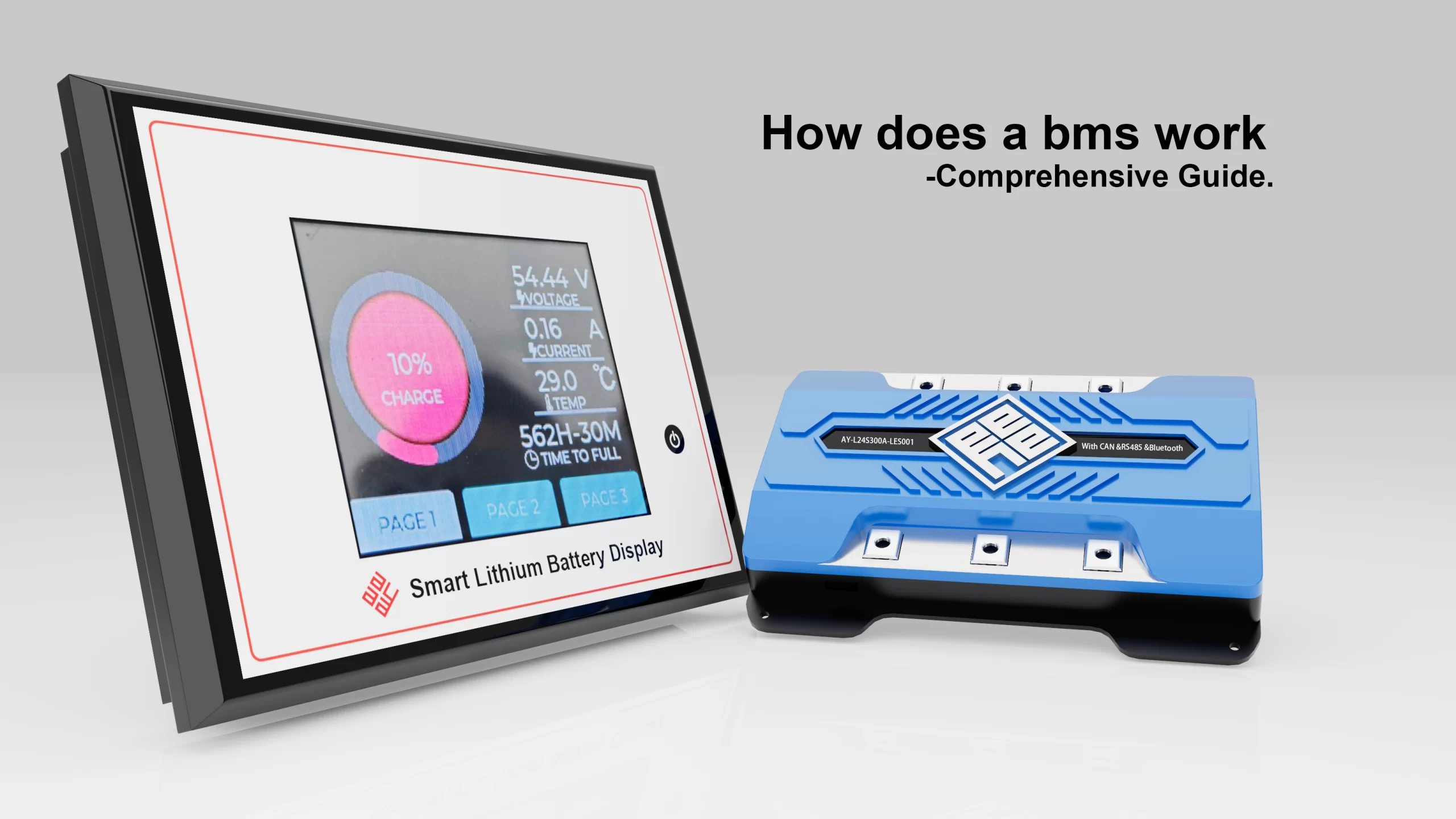
ДомО насСОБЫТИЯ И НОВОСТИПонимание схемы подключения BMS: от управления MOSFET до балансировки ячеек
Понимание схемы подключения BMS: от управления MOSFET до балансировки ячеек
12199
Понимание схемы подключения BMS: от управления MOSFET до балансировки ячеек
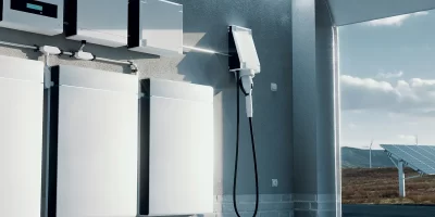
To ensure safety, dependability, and efficiency in contemporary lithium-ion and lithium-polymer battery systems, the Battery Management System (БМС) is essential. The BMS controls how energy is charged, discharged, and balanced even if battery cells retain energy. Studying the BMS connection diagram, which shows the current flow, protective component location, and balancing circuit integration, is essential to fully comprehending how a BMS operates.
Therefore, what makes balance control, MOSFET control, and BMS protection functions so crucial? The fundamental ideas behind BMS connection diagrams will be examined, along with the circuit’s different levels, components, and how these connection diagrams relate to the real safety and performance benefits of lithium-ion batteries.
Overview of BMS Boards and Protection Functions
In essence, a battery pack’s primary control center is a BMS board. Its main duties include:
Monitoring: Tracking voltage, current, and temperature of each cell or group of cells.
Protecting: Preventing overcharging, over-discharging, short circuits, and overcurrent events.
Балансирование: Equalizing charge levels across cells to extend the battery’s overall lifespan.
Communicating: Sending diagnostic and operational data to external devices, such as controllers or smart systems.
These functionalities become more apparent when seen through a BMS connection diagram. Every wire, MOSFET, resistor, and sensor is positioned carefully to carry out a particular control or protection task.
Analyzing a BMS Connection Diagram
A bms connection diagram typically includes:
Battery Cell Connections: Each cell or group of cells is connected via balance leads, allowing the BMS to monitor voltage levels precisely.
MOSFET Control Section: Responsible for switching on/off charging and discharging paths.
Protection Circuits: These include overvoltage, undervoltage, overcurrent, and short-circuit protections.
Thermal Sensors: Integrated thermistors or temperature sensors feed data back to the BMS.
Балансирующие цепи: Either passive (resistive) or active (redistribution) methods are shown in the diagram.
Engineers can learn how energy moves through a system, how to avoid failures, and where to maximize efficiency by examining a connection diagram.
A number of considerations become crucial when using a bms connection diagram with lithium-ion batteries:
Voltage per Cell: Lithium-ion cells operate within 3.0V–4.2V typically, and the diagram ensures each cell is monitored within this safe window.
Series Configuration: For example, a 12S pack has 12 cells in series, and each needs to be represented in the diagram with an individual sensing connection.
Pack Terminals: The positive and negative terminals are routed through MOSFETs and safety fuses.
Balancing Wires: The diagram shows each lead returning to the BMS to measure and balance cell voltage.
Engineers can use this diagram as a guide for assembly and troubleshooting, making sure all connections are made correctly and all protective features are turned on.
In-Depth Look: Battery Protection, Protection Circuit, and Cell Balancing
Battery Protection
Protecting cells from hazardous operating circumstances is a BMS’s primary duty. Redundancy is ensured via the layering of protection functions. For instance, over-discharge detection prevents irreversible capacity loss, and over-charge detection prevents catastrophic thermal runaway.
Protection Circuit
The protection circuit is made up of MOSFETs, comparators, and resistors, as shown in a bms connection diagram. These make sure that the circuit cuts the charging line if an anomaly is found, such as a cell exceeding the safe voltage.
Баланс клеток
Since cells naturally drift in voltage during numerous cycles of charge and discharge, balancing is another essential function. Active balancing redistributes charge among cells, whereas passive balancing uses resistors to bleed off surplus charge from higher-voltage cells. Which balancing technique is employed and how it works with the system will be indicated by a well-designed connection diagram.
How Does a Lithium-Ion Battery BMS Circuit Work?
Why Connect Multiple MOSFETs?
The core of BMS switching functions are MOSFETs. To manage higher current loads or lower resistance, several MOSFETs are often coupled in parallel in designs. Whether the design use parallel MOSFETs for high-current applications or back-to-back MOSFETs for bidirectional control (charge/discharge) is indicated by a bms connection diagram.
How MOSFETs are Controlled
Driver ICs receive signals from the BMS microcontroller and control MOSFET gates. For example:
If overcharge is detected, the MOSFET controlling charging is switched off.
If overcurrent occurs, discharge MOSFETs are disabled.
These gate-driving pathways are shown in the connection diagram, which aids engineers in determining precisely how and when protection activates.
Components Used in a BMS Module
A standard BMS connection diagram shows the following important elements:
Транзисторы МОП: For switching charge/discharge paths.
Shunt Resistors: For current sensing.
Voltage Monitoring ICs: Measure individual cell voltages.
Balancing Resistors or Capacitors: Enable cell balancing.
Thermistors: Monitor temperature for thermal protection.
Connectors: Ensure proper wiring between cells and the BMS.
Every part plays a specific purpose, and the schematic guarantees that they are all correctly integrated into the larger circuit.
Protection Functions of a BMS Module
Overcharge Protection
The BMS cuts off charging MOSFETs when a cell reaches its maximum voltage, which is usually 4.2V for Li-ion batteries. This safety path is prominently marked in the BMS connection diagram.
Over-Discharge Protection
Cells are kept from falling below 3.0V by cutting off the discharge channel. This keeps the battery’s chemistry intact and increases its useful life.
Overcurrent and Short-Circuit Protection
Excessive current is extremely harmful, regardless of whether it results from a short circuit or a load issue. Shunt resistors and sensor integrated circuits are used by the BMS to identify anomalous current flow. The discharge MOSFETs promptly shut off if thresholds are crossed.
Key Considerations When Using a BMS Connection Diagram
Engineers should take into account the following when working with or designing using a BMS connection diagram:
Voltage Rating: Ensure the BMS matches the pack configuration (e.g., 4S, 6S, 12S).
Текущая мощность: MOSFET and trace sizing must match the application’s current demands.
Balancing Method: Decide between passive and active balancing based on efficiency and cost.
Thermal Management: Include adequate sensors and design for heat dissipation.
Regulatory Compliance: Connection diagrams must account for functional safety standards like ISO 26262 or IEC 62619.
Scalability: Modular diagrams allow for easy expansion to larger packs.
Neglecting these elements may result in a less reliable system, a higher chance of failure, and possible safety risks.
Часто задаваемые вопросы
Q:How is BMS connected?
A:Two battery cells are connected in series for a 2S BMS connection. By connecting one cell’s positive terminal to the other’s negative terminal, this arrangement essentially doubles the voltage output while keeping the capacity of a single cell.
Q:What is a BMS connector?
A:This battery management system keeps lithium-ion batteries, which are utilized in automobile batteries, from overcharging or overdischarging. A lot of our connectors are utilized to connect the battery to the BMS.
Q:What is the CD and FD on BMS?
A:The BMS has two pads with the designations CD and FD. The signal that indicates the charging state as finished is called CD, and the signal that indicates the discharge status is called FD.
Q:What is the sequence of BMS wiring?
A:Cells Negative -> B- on BMS -> C- on BMS -> Shunt (if applicable) -> Negative Bus Bar -> Loads.The most typical layout is that one.
Q:Is it safe to bypass BMS?
A:In order to get around a BMS, the mechanism that controls the battery pack’s operations must be disconnected or disabled. This may result in a number of risks: Risks to Safety: The battery is vulnerable to circumstances that could result in thermal runaway without a BMS, which could result in fires or explosions.
Q:How to know which wire to connect?
A:The typical colors for home wiring are as follows:
Hot wire is black.
Ground wire is green.
Red: utilized with larger appliances, this is the supplementary hot wire.
White: a neutral wire.
Q:What is BMS wiring?
A:Specialized cables known as BMS (Building Management System) cables are used to connect different parts of a building management system. All multi-conductor cables coated in PVC, LSZH (FRNC), or LSF are appropriate for use with Building Management Systems (BMS), which include Sound, Audio, Security, Safety, Control, and.
Q:What is the 20S battery layout?
A:A series arrangement of 20 battery cells is denoted by the term “20S.” In particular, it shows that a battery pack is made up of 20 separate 18650 battery cells connected in series. Batteries that are connected in series have higher voltages but the same capacity (measured in ampere-hours, or Ah) as a single cell.
Заключение
More than merely a technical illustration, a bms connection diagram serves as a guide for contemporary energy storage systems’ efficiency, dependability, and safety. Engineers can create and maintain battery systems that function reliably under demanding circumstances by examining the positioning of MOSFETs, comprehending balancing techniques, and appreciating the function of each safeguard circuit.
The significance of comprehending and using these diagrams cannot be emphasized as energy applications—from electric automobiles to industrial storage to drones—become more intricate. Longer battery life, lower maintenance costs, and adherence to safety regulations are all guaranteed by a well-designed BMS.
Enterprises like Ayaa Technology offer high-performance BMS modules that are made to blend in perfectly with different battery architectures for enterprises looking for cutting-edge BMS solutions. They provide dependable routes to creating safer and more intelligent energy systems because of their proficiency in safety, performance, and communication protocols.