- Industries


Home Backup & Garden BMS
View More >
Electric Forklift BMS
View More >
Golf Cart BMS
View More >
Electric Two-wheeler BMS
View More >
Aviation & UAV BMS
View More >
BMS For Power Tools
View More >
Medical Equipment BMS
View More >
AYAA offers high-quality BMS batteries designed for LiFePO4 replacements. As a leading China manufacturer, AYAA provides customized solutions and reliable product supply.
With the accelerating trend of electrification in marine equipment, marine BMS battery systems have become the core component of modern ship power systems. Unlike terrestrial applications, the marine environment presents more stringent requirements for battery systems—not only must they withstand harsh conditions such as salt spray corrosion, high humidity, and severe vibration, but they must also possess high levels of safety and reliability. Marine BMS battery systems equipped with advanced Battery Management Systems (BMS) provide safe and reliable power assurance for various vessels including yachts, commercial fishing boats, and offshore platforms through real-time monitoring of cell status, execution of multiple protection functions, and intelligent management capabilities.
This comprehensive guide will provide an in-depth analysis of the technical principles, structural design, application scenarios, and selection and maintenance considerations of marine BMS battery systems, helping marine engineers, shipbuilders, and ship owners fully understand this critical technology and provide professional guidance for the sustainable development of marine equipment.
A BMS battery refers to a battery pack equipped with a Battery Management System (BMS). Compared to traditional ordinary batteries, BMS battery systems possess higher intelligence, safety, and controllability. Ordinary batteries are mostly single-cell forms that lack real-time monitoring of parameters such as voltage, current, and temperature, making them prone to safety issues in high-capacity or high-rate usage scenarios.
In contrast, BMS battery systems integrate an electronic system that can collect and regulate cell status in real-time, executing functions such as overvoltage protection, undervoltage protection, overcurrent protection, short circuit protection, temperature control, and balancing management.
Ordinary batteries are suitable for low-requirement applications such as remote controls and small LED devices. However, BMS battery systems are standard configurations in fields such as electric vehicles, energy storage systems, medical equipment, and high-power tools. In lithium battery systems, cell consistency and thermal runaway management are particularly important, making the role of BMS indispensable.
Furthermore, BMS systems can interact with external devices through communication interfaces such as CAN, UART, and SMBus, enabling remote monitoring, power prediction, and cloud management, serving as key infrastructure for building intelligent energy systems.
The working principle of a BMS battery can be divided into six major modules: monitoring, voltage balancing, protection, control, data communication, and fault diagnosis. First, the BMS monitors the voltage, current, and temperature of each individual cell through sampling circuits. Once any parameter exceeds the safety threshold, the system immediately activates protection mechanisms, such as disconnecting the load, cutting off the charging path, or issuing alarms.
During the charging process, if there is inconsistency in cell voltages, the BMS corrects the voltage through active or passive balancing circuits to ensure overall battery pack consistency, thereby extending service life and improving energy efficiency. The control section manages the battery's charge and discharge paths through components such as MOSFET relays.
Additionally, modern BMS systems are equipped with MCU (Microcontroller Units) or embedded systems that can predict SOC (State of Charge) and SOH (State of Health) through software algorithms. This data can be transmitted to external systems via CAN bus or Bluetooth, enabling remote monitoring, historical data tracking, and cloud management. Overall, the BMS serves as the brain of the battery system, being the core component that ensures safe, stable, and intelligent operation.
In the following application scenarios, using a BMS battery system is essential and irreplaceable:
When systems employ multi-series or parallel lithium battery structures, the status between cells easily becomes inconsistent, such as voltage drift or temperature runaway. BMS battery systems can achieve cell balancing, protection, and unified management.
In fields such as electric vehicles, medical devices, and energy storage power stations, there are strict requirements for thermal management, short circuit protection, and data visualization that ordinary batteries cannot meet. BMS battery systems must be introduced for safety supervision.
Industrial robots, AGV automatic transport vehicles, and intelligent building energy storage systems require battery systems to upload data or receive commands through communication interfaces. BMS battery systems can complete communication functions through protocols such as CAN/485.
In long-term operating systems such as photovoltaic energy storage and grid frequency regulation, BMS battery systems help operators develop maintenance plans and avoid sudden failures through SOH prediction and balancing functions.
Therefore, whenever projects involve high power, multi-series configurations, intelligent communication, or medium to high safety requirements, BMS battery systems are no longer optional but core configurations.
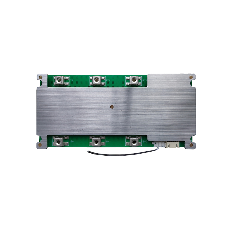
The internal structure of a BMS battery can be divided into three major components: cell units, management system mainboard (BMS main controller), and auxiliary modules (such as sampling lines, temperature sensors, communication interfaces).
Usually composed of multiple series or parallel 18650, 21700, or LiFePO4 cells, each cell is connected through nickel strips, electrical connection pieces, or copper bars, arranged into battery packs.
This is the core of the BMS battery system, including MCU controller, voltage sampling module, current detection circuit, temperature detection interface, MOS tube control circuit, and balancing circuit. High-end BMS systems are also equipped with EEPROM for data storage and RTC for real-time clock management.
Structurally, the BMS mainboard is usually located on one side or top of the battery pack, connected to each series cell through flat connectors and sampling lines for status sampling and regulation. Good structural design can significantly improve system safety and heat dissipation capabilities.
The charging and discharging process of BMS battery systems is controlled and regulated in real-time by their management systems, ensuring the entire system operates efficiently under safe and stable conditions.
1. After power connection, the BMS first detects environmental temperature and initial battery status
2. Enter constant current charging phase, where current is limited but voltage gradually rises, with BMS monitoring series voltage and temperature in real-time
3. After reaching set voltage, enter constant voltage phase where current begins to gradually decrease, while BMS activates balancing mechanism to correct cell voltage differences
4. When all cells achieve consistency, BMS closes charging circuit and signals full charge completion
1. After discharge initiation, BMS opens discharge circuit and continuously monitors load current, cell voltage, and temperature
2. If system detects any series cell voltage too low or current too high, it immediately disconnects discharge circuit to prevent damage
3. Throughout the discharge process, BMS dynamically calculates SOC values based on current and capacity changes and provides real-time output
Through these mechanisms, BMS battery systems ensure safety control during charging and discharging processes, reasonable power distribution, and system life extension. This process is particularly crucial in applications with high stability requirements such as electric vehicles, UPS energy storage, and industrial control equipment.
The safety protection mechanism of Battery Management Systems (BMS) is key to ensuring reliable operation of lithium battery packs. Modern BMS battery systems achieve comprehensive battery protection through multi-layer defense architecture, mainly including voltage protection, current protection, and temperature protection modules.
Case study: A power battery pack reduced thermal runaway accident rates from 0.1% to below 0.001% through three-level protection design.
SOC (State of Charge) estimation is the core algorithm of BMS battery systems, with accuracy directly affecting range prediction accuracy. Due to battery non-linear characteristics, SOC estimation has always been an industry challenge.
|
Method |
Principle |
Advantages |
Disadvantages |
Application Scenarios |
| Ampere-hour Integration | Current-time integration | Simple implementation | Error accumulation | Short-term estimation |
| Open Circuit Voltage | OCV-SOC curve | Absolute reference | Requires rest | Calibration scenarios |
| Kalman Filter | State space model | Good dynamics | Complex calculation | Automotive batteries |
| Neural Network | Data-driven | Strong adaptability | Requires big data | Intelligent BMS |
1. Initial SOC calibration (measure OCV after 6-hour rest)
2. Real-time current integration (coulomb counting)
3. Dynamic correction (combined with temperature, aging factors)
4. Regular calibration (full charge/deep discharge nodes)
Data: Advanced BMS battery systems can control SOC estimation error within ±3% (NEDC conditions).
Electric vehicle BMS battery systems must meet ASIL-D functional safety levels with the following characteristics:
Energy storage system BMS battery configurations need to focus on:
Example: 1MWh energy storage system recommended configuration:
Choosing a BMS battery requires considering six core parameters:
1. Battery type (ternary/LiFePO4/lithium titanate)
2. Series-parallel quantity (e.g., 16S1P)
3. Maximum operating current (continuous/peak)
4. Communication interface requirements (CAN/RS232, etc.)
5. Environmental conditions (temperature/humidity/vibration)
6. Certification requirements (CE/UL/GB, etc.)
|
Item |
Consumer Grade |
Industrial Grade |
Automotive Grade |
| Accuracy | ±5% | ±3% | ±1% |
| Lifespan | 3 years | 5 years | 8 years |
| Price | $10-50 | $50-200 | $200+ |
When selecting appropriate BMS battery systems for different applications, comprehensive evaluation must be based on scenario power requirements, safety levels, communication capabilities, and operating environment parameters. For example, in electric vehicles, BMS battery systems must have high-speed CAN communication, redundant protection mechanisms, SOC/SOH intelligent estimation, and multi-zone thermal management capabilities. In home energy storage systems, greater emphasis is placed on cell balancing efficiency, low-power standby, and RS485 communication interface stability.
Therefore, BMS battery selection decisions should be based on system structure, cell type, current level, environmental temperature, and maintenance convenience, requiring systematic comparison and parameter matching.
BMS battery installation requires precision and rigor to avoid misconnection or incomplete connections that could cause cell damage, system short circuits, or performance abnormalities.
1. Confirm cell arrangement structure: Clarify series-parallel configuration (e.g., 13S2P means 13 series 2 parallel) and ensure tight, secure connections between cells
2. Connect sampling harness: Connect positive terminals of each series cell sequentially to BMS battery voltage detection interfaces (typically JST connectors), maintaining correct order
3. Connect main power lines: Connect main output positive and negative terminals to corresponding BMS battery P+ and P- terminals, adding fuses or circuit breakers if necessary
4. Install temperature probes: Place temperature sensors at cell core positions to ensure accurate thermal management module sampling
5. Connect main control module: If BMS battery has power button or wake-up function, manually start system and enter initial settings interface
6. Communication port connection: If equipped with CAN, UART, or Bluetooth modules, ensure correct connections and perform initialization testing
After installation completion, check all functions including overvoltage/undervoltage protection, balancing activation, current limiting, and communication debugging to ensure proper operation before use.
Correct usage and scientific maintenance are key to ensuring long-term stable operation of BMS battery systems. Since BMS integrates multiple electronic function modules, improper use may cause false protection, charging/discharging abnormalities, or even cell damage.
Through these standardized usage and maintenance methods, not only can battery safety factors be improved, but system overall lifecycle can be significantly extended.
BMS battery performance highly depends on reasonable parameter configuration, especially under different cell types, series-parallel structures, and application environments, requiring precise setting of multiple key parameters.
Through reasonable parameter settings and continuous fine-tuning based on system measurement data, BMS battery systems can achieve optimal efficiency, stability, and protection accuracy.
While BMS battery systems have slightly higher initial costs compared to ordinary batteries, their long-term value far exceeds the investment.
BMS battery systems monitor cell status in real-time, avoiding risks such as overcharge, overdischarge, short circuit, and overtemperature
Through active/passive balancing management, maintain cell consistency and reduce capacity loss
BMS battery systems support communication protocols for integration into EMS or cloud platforms
Flexible selection based on voltage and current levels for various applications
Accurate power estimation avoids excessive charging or premature discharge
Although BMS battery systems have higher initial investment, through improved safety, extended life, reduced maintenance costs, and enhanced operational efficiency, average payback period is 1-1.5 years, far superior to non-BMS systems' overall economic benefits.
Modern intelligent BMS battery systems have evolved from basic protection to AI-capable battery managers with core functions including:
1. AI Health Prediction: LSTM neural networks analyze historical data with 20+ dimensional inputs
2. Adaptive Learning: Update battery model parameters every charge/discharge cycle
3. User Habit Learning: Support automatic optimization of charge/discharge curves
Case study: A brand's intelligent BMS battery achieved 40% life extension and 98.7% anomaly warning accuracy through AI algorithms.
1. Charging Phase: Use original chargers, 0-45°C environment temperature
2. Discharging Phase: Control discharge depth (recommend >20% SOC)
3. Storage Phase: Maintain 40-60% charge, supplement every 3 months
Data shows proper operation can reduce accident rates by 90%.
1. Voltage sampling accuracy ±1mV
2. Balancing current ≥200mA
3. Protection level IP67+
4. Communication packet loss <0.1%
5. Fault record capacity ≥1000 entries
6. UL/IEC certification compliance
1. Communication interruption (38%)
2. Voltage sampling abnormalities (25%)
3. Balancing failure (18%)
4. Temperature detection faults (12%)
5. False protection triggering (7%)
1. Deep discharge (<10% SOC)
2. High temperature operation (>45°C)
3. Improper charging strategies
Results show cycle life can be improved from 500 to 1500 cycles through proper maintenance.
Marine BMS battery systems, as important drivers of marine electrification, are evolving toward higher safety, stronger environmental adaptability, and greater intelligence. Through comprehensive analysis in this guide, modern marine BMS battery systems not only solve many limitations of traditional lead-acid batteries in marine environments but also achieve precise SOC estimation, dynamic balancing management, and predictive maintenance through advanced battery management technology.
Whether for comfortable yacht cruising or efficient commercial vessel operations, proper selection and correct use of marine BMS battery systems will bring significant economic benefits and safety assurance. With continuous breakthroughs in marine new energy technology, we have reason to believe that more intelligent, environmentally friendly, and efficient marine BMS battery systems will inject strong momentum into the green transformation of the marine industry, driving marine equipment toward a more sustainable future.
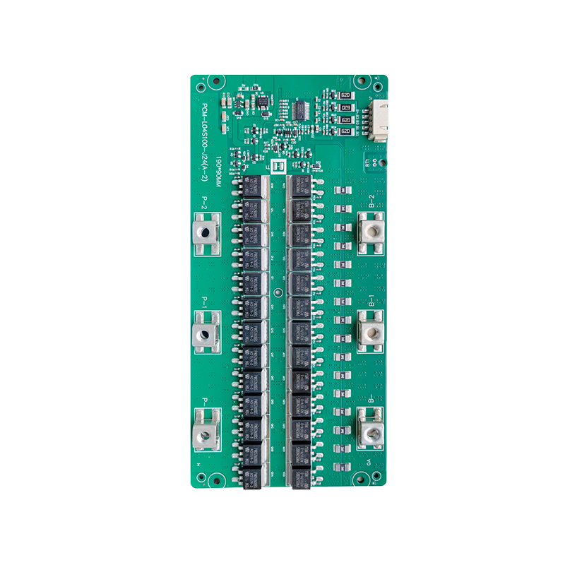
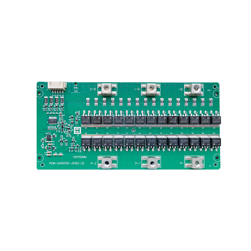
| Model: PCM-L04S100-J24 | ||
| Test item(Test at normal temperature 25±2℃ ) | Criterion | |
| Voltage | Charging voltage | DC:13.8V~16.8V CC/CV(3.45V~4.2V/Cell)4s |
| Supply Current | Normal operating mode current:Fuel gauge in NORMAL mode. ILOAD >Sleep Current | ≤50uA |
| Maximal continuous charging current | 20-100A | |
| Maximal continuous discharging current | 20-100A | |
| Balance current for single cell | 36-42mA | |
| Over-charge Protection (single cell) | Balance voltage for single cell | 3.6-4.20V |
| Over charge detection voltage | 3.6-4.40V | |
| Over charge detection delay time | 0.5S—2S | |
| Over charge release voltage | 3.5-4.30V | |
| Over discharge protection (single cell) | Over discharge detection voltage | 2.4-3.0V |
| Over discharge detection delay time | 10—200mS | |
| Over discharge release voltage | 2.6-3.4V | |
| Current protection (Battery pack) | Discharge Over current detection current | 60-300A |
| Detection delay time | 5ms—20ms | |
| Release condition | Cut load,Auto Recovery | |
| Short protection | Detection condition | Exterior short circuit |
| Detection delay time | 200-600us | |
| Release condition | Cut load | |
| Resistance | Main loop electrify resistance | ≤65mΩ |
| Temperature | Operating Temperature Range | -40~+85℃ |
| Storage Temperature Range | -40~+125℃ | |
| SIZE: L190 *W90 *T14.5 mm | ||
| NTC:10K NTC*2PCS Temperature switch:/ Weak current switch:/ Activation Method:/ | ||