- Industries


Home Backup & Garden BMS
View More >
Electric Forklift BMS
View More >
Golf Cart BMS
View More >
Electric Two-wheeler BMS
View More >
Aviation & UAV BMS
View More >
BMS For Power Tools
View More >
Medical Equipment BMS
View More >
AYAA provides high-quality battery BMS for LiFePO4 and lead-acid battery replacements. We offer wholesale options, OEM/ODM services, and reliable factory supply.
In today's rapidly evolving lithium battery technology landscape, Battery Management Systems (BMS) have emerged as critical components for ensuring battery safety and enhancing performance. Whether powering electric vehicle battery packs or residential energy storage systems, battery BMS serves as the essential "guardian" of modern battery applications. This comprehensive guide explores the working principles of battery BMS, analyzing how millisecond-level voltage monitoring (±1mV precision) and intelligent balancing technology (±20mV voltage differential control) extend battery lifespan. We'll compare battery BMS selection criteria across different applications, from 200A high-current handling to CAN bus communication protocols, presenting the most practical technical insights for engineers, technology enthusiasts, and end users alike.
Battery Management System (BMS) functions as the "intelligent brain" of lithium battery packs, continuously monitoring critical parameters including voltage, current, and temperature to ensure safe operation and extend battery life. The core value of battery BMS lies in addressing two major lithium battery risks: thermal runaway (such as fires caused by overcharging) and capacity degradation (reduced available capacity due to cell imbalance). For electric vehicles, battery packs without proper battery BMS may achieve fewer than 500 charge cycles, while systems equipped with advanced battery BMS can exceed 3,000 cycles.
The importance of battery BMS manifests across three critical dimensions:
Battery BMS operates through a "monitor-decide-execute" closed-loop system comprising three integrated layers:
Balancing Strategy: During charging phases, the battery BMS activates resistive balancing (100mA), switching to active balancing (300mA) during rest periods for optimal efficiency.
Battery BMS hardware architecture typically employs modular design, incorporating three primary functional modules:
MOSFET Arrays: Six parallel IRFB4110 MOSFETs provide 200A current handling capability with Rdson <0.5mΩ for minimal power loss.
Battery BMS overcharge and overdischarge protection operates through multi-level interlocking mechanisms:
1. Voltage Threshold Activation: When any cell reaches 4.25V (adjustable), battery BMS reduces charging current by 50%
2. Secondary Protection: Voltage continues rising to 4.3V, battery BMS disconnects charging MOSFET (response time <100ms)
3. Fault Lockout: Requires manual reset or specific conditions (voltage drops to 4.0V) for system recovery
|
Type |
Balancing Current |
Efficiency |
Cost |
Application Scenario |
| Passive Balancing | 50-100mA | 60% | $0.08/cell | Low-speed electric vehicles |
| Active Balancing | 300mA-1A | 85% | $0.80/cell | Premium energy storage/EVs |
| Inductive Balancing | 2A+ | 90% | $1.60/cell | Aerospace applications |
Battery BMS technology evolution drives differentiated applications across various sectors:
Selecting appropriate battery BMS presents challenges for many users who struggle with identifying critical parameters. Successful selection requires comprehensive consideration of battery type, series-parallel configuration, maximum current, communication protocols, and application scenarios.
Battery BMS applications in electric vehicles or energy storage systems often require CAN, UART, or RS485 communication interfaces for real-time data exchange with host controllers. Industrial applications may additionally require SOC estimation, historical data recording, and intelligent balancing management functions.
Selection processes should prioritize system stability and future scalability. Users should reference manufacturer technical manuals during initial design phases to properly configure battery BMS parameters, avoiding resource waste from subsequent replacements.
Proper battery BMS installation and operation directly impacts system stability, safety, and service life. Incorrect wiring, improper power-up sequences, and environmental factors can cause battery BMS malfunctions or even battery thermal runaway.
1. Battery State Verification: Ensure all battery cells maintain consistent voltage with differences not exceeding ±0.05V before installation
2. Temperature Sensor Connection: Prioritize NTC temperature monitoring circuit connections to enable real-time temperature data acquisition
3. Sequential Balance Wire Connection: Connect cell strings according to manual specifications (B1, B2, B3...) in proper sequence
4. Main Current Path Connection: Connect battery BMS P- (discharge negative), C- (charge negative), and B- (battery negative) terminals
5. System Power-Up and Activation: For intelligent battery BMS, use debugging tools or host software to activate systems and calibrate parameters
6. Multi-Point Verification: Check connection stability, wire gauge compatibility, and terminal temperature conditions
Additional considerations include battery BMS heat dissipation and waterproof protection, particularly in outdoor or high-temperature environments. Recommend installing aluminum heat sinks or sealed protective enclosures. Avoid hot-plugging batteries during operation to prevent high-current damage to MOSFETs or circuit boards.
Battery BMS systems inevitably encounter various issues during long-term operation, including charging/discharging failures, persistent alarms, and communication anomalies. Accurate problem diagnosis and timely corrective measures are essential for maintaining safe, stable system operation.
These issues typically result from wiring errors or unresolved protection states. Check whether battery BMS is in sleep mode, confirm battery voltage meets startup thresholds, or verify if overdischarge protection remains active.
When battery BMS continuously indicates voltage anomalies, investigate cell voltage differentials and identify aging battery cells. Utilize balancing functions for forced voltage adjustment or replace defective cells as necessary.
Commonly caused by MOSFET damage or P-terminal current anomalies. Use multimeters to test P-terminal voltage variations or replace output circuit components.
For battery BMS supporting CAN or RS485 protocols, communication interruptions often result from poor interface connections, mismatched baud rate settings, or data frame conflicts. Utilize host diagnostic tools for systematic troubleshooting and firmware updates when necessary.
Maintenance procedures must strictly follow anti-static operation protocols, especially when handling chip areas or MOSFET components. Maintain detailed fault handling records for future analysis and documentation.
As lithium-ion battery applications expand across electric vehicles (EVs), energy storage systems (ESS), and industrial equipment, the Battery BMS (Battery Management System) remains critical for ensuring safety, efficiency, and longevity. In 2025, the global Battery BMS market is projected to reach USD 9.84 billion, driven by EV adoption and renewable energy integration. This guide highlights the top Battery BMS brands, with a special focus on AYAATECH, a leader in innovative, customizable, and high-performance Battery BMS solutions.
AYAATECH (Shenzhen Ayaa Technology Co., Ltd.) is a premier choice for Battery BMS solutions, offering over 17 years of expertise and a portfolio of 400+ models from 1S to 35S, with currents from 1A to 320A. Here’s why AYAATECH excels:
AYAATECH’s AI-driven Battery BMS solutions, including predictive diagnostics, align with 2025 trends like solid-state battery integration and enhanced safety standards (UL/IEC).
AYAATECH’s Battery BMS solutions outshine competitors due to:
AYAATECH excels across these criteria, offering tailored Battery BMS solutions with robust certifications and versatile communication protocols.
Many beginners confuse "Protection Boards" with "Battery Management Systems," sometimes considering them identical products. However, these systems differ fundamentally in structural design, functional logic, and application domains.
Protection boards typically lack external communication interfaces, while battery BMS systems commonly support UART, CAN, or Bluetooth for host system communication, enabling remote monitoring, firmware updates, and parameter modifications.
Protection boards suit low-cost products like LED lights, electric toys, and small flashlights. Battery BMS systems serve energy storage stations, electric vehicles, drones, and premium equipment requiring enhanced battery life and safety.
Therefore, choose protection boards for basic charge-discharge protection needs, but prioritize comprehensive battery BMS systems for applications demanding controllability, safety, and maintainability.
Electric vehicle battery BMS represents the "central nervous system" of new energy vehicles, with technical complexity far exceeding conventional energy storage systems. Power battery BMS core challenges include:
CAN bus serves as the "main artery" for battery BMS vehicle communication, with technical implementation spanning multiple critical layers:
Battery BMS maintenance requires establishing periodic maintenance schedules, categorized as follows:
Battery BMS investment returns require full lifecycle assessment:
|
Item |
Basic Battery BMS |
Premium Smart Battery BMS |
| Initial Cost | $120-240 | $480-800 |
| Annual Maintenance | $32 | $8 |
| Battery Lifespan | 800 cycles | 1500 cycles |
| Residual Value Rate | 30% | 50% |
A shared battery swapping station using premium battery BMS achieved:
Battery BMS technology advances toward three breakthrough directions:
Through this comprehensive exploration, we clearly recognize the core value of battery BMS in modern battery systems: serving not only as safety guardians preventing overcharge and overdischarge, but as intelligent managers optimizing battery performance. From basic protection boards to advanced battery BMS supporting AI algorithms, technological progress continuously expands application boundaries.
Selecting appropriate battery BMS requires considering multiple factors including battery type, current requirements, and communication protocols, while proper installation and maintenance significantly extend system lifespan. With emerging technologies like wireless battery BMS and silicon carbide drives, future battery BMS will become increasingly intelligent and integrated.
Mastering this knowledge enables informed decision-making for diverse battery applications, ensuring optimal performance, safety, and longevity across residential, commercial, and industrial energy storage solutions. The evolution of battery BMS technology continues driving innovation in electric mobility, renewable energy integration, and smart grid applications worldwide.
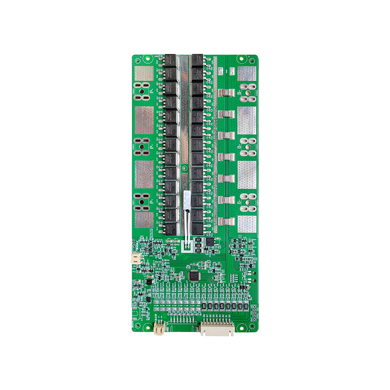
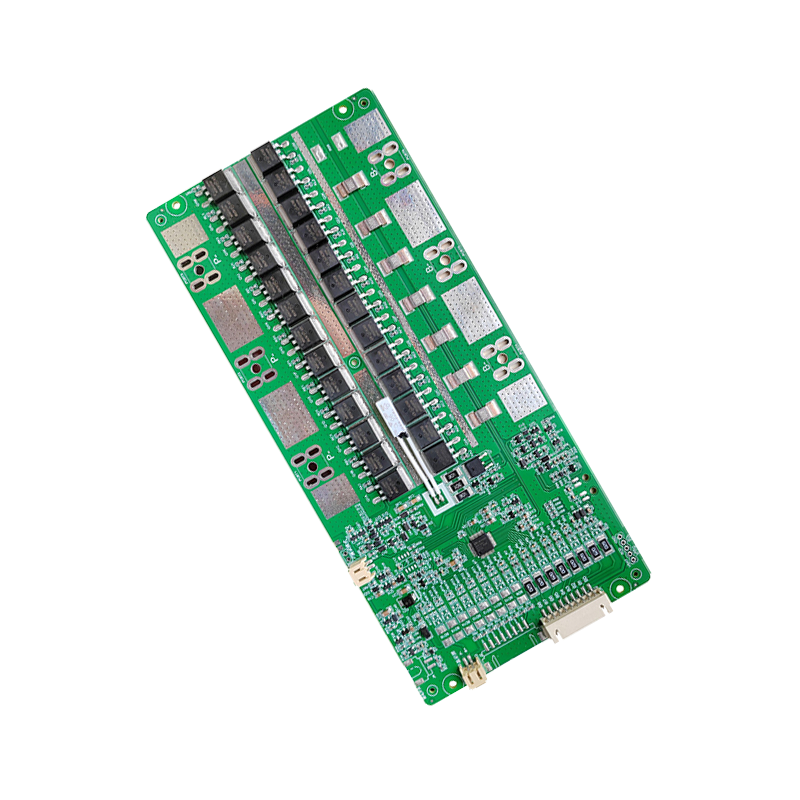
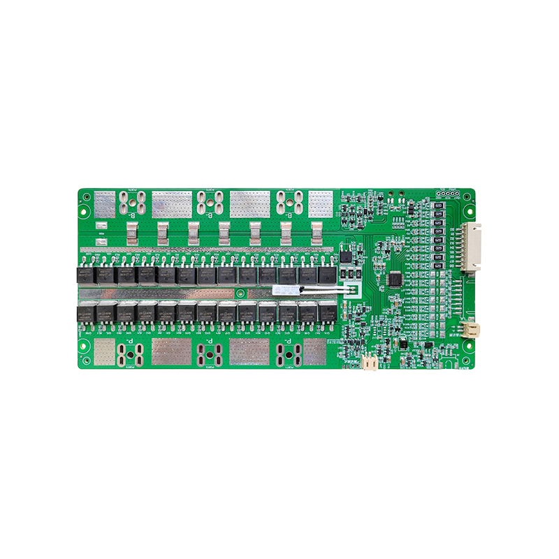
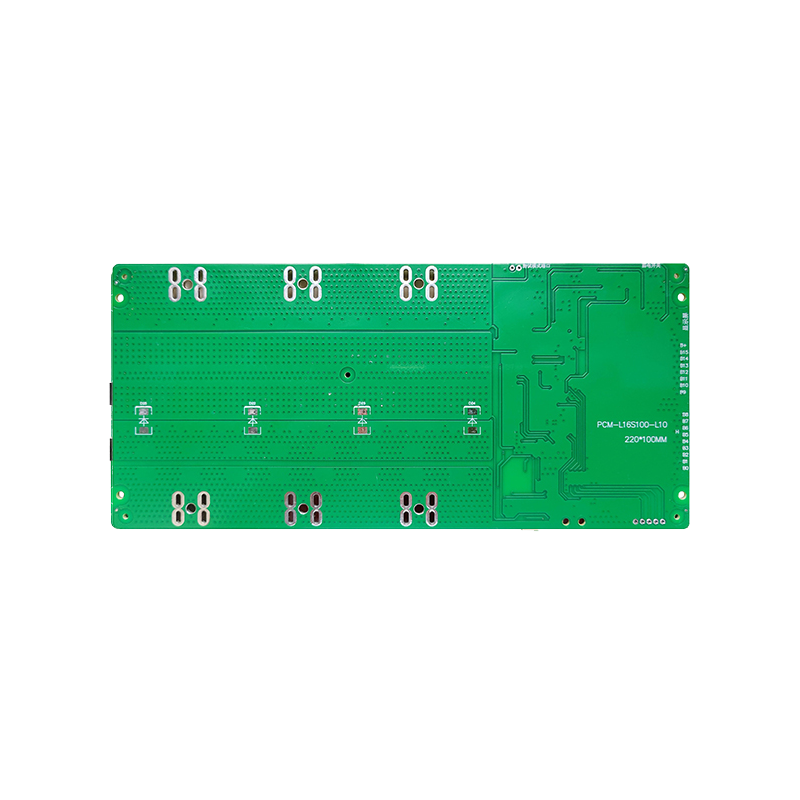
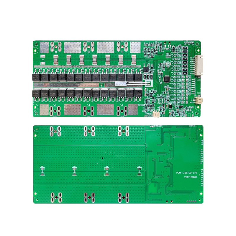
| Model: PCM-L16S100-L10 | ||
| Test item(Test at normal temperature 25±2℃ ) | Criterion | |
| Voltage | Charging voltage | DC:55.2V~67.2V CC/CV(3.45V~4.2V/Cell)16s |
| Supply Current | Normal operating mode current:Fuel gauge in NORMAL mode. ILOAD >Sleep Current | ≤50uA |
| Maximal continuous charging current | 30-100A | |
| Maximal continuous discharging current | 30-100A | |
| Balance current for single cell | 36-42mA | |
| Over-charge Protection (single cell) | Balance voltage for single cell | 3.6-4.20V |
| Over charge detection voltage | 3.6-4.40V | |
| Over charge detection delay time | 0.5S—2S | |
| Over charge release voltage | 3.5-4.30V | |
| Over discharge protection (single cell) | Over discharge detection voltage | 2.4-3.0V |
| Over discharge detection delay time | 10—200mS | |
| Over discharge release voltage | 2.6-3.4V | |
| Current protection (Battery pack) | Discharge Over current detection current | 90-300A |
| Detection delay time | 5ms—20ms | |
| Release condition | Cut load,Auto Recovery | |
| Short protection | Detection condition | Exterior short circuit |
| Detection delay time | 200-600us | |
| Release condition | Cut load | |
| Resistance | Main loop electrify resistance | ≤65mΩ |
| Temperature | Operating Temperature Range | -40~+85℃ |
| Storage Temperature Range | -40~+125℃ | |
| Pre-charge/discharge | ||
| SIZE: L220 *W100 *T15 mm | ||
| NTC: 10K NTC Temperature switch:90℃ Weak current switch:YES Activation Method:/ | ||