- Industries


Home Backup & Garden BMS
View More >
Electric Forklift BMS
View More >
Golf Cart BMS
View More >
Electric Two-wheeler BMS
View More >
Aviation & UAV BMS
View More >
BMS For Power Tools
View More >
Medical Equipment BMS
View More >
AYAA, a China-based manufacturer, provides high-quality 13S BMS for lithium-iron-phosphate batteries. We offer customized solutions, wholesale options, and reliable factory supply for 16V-48V battery protection.
In high-voltage lithium battery applications, such as 48V or 54.6V systems, the 13S BMS (13 Series Battery Management System) serves as the critical "brain" and "guardian" of the battery pack. The 13S BMS employs high-precision ADC to monitor each cell’s voltage (2.5V–4.2V), instantly disconnects circuits via MOSFETs during risks like overcharge (>4.25V), over-discharge (<2.8V), overcurrent, short-circuit, or overheating, and incorporates active or passive balancing to maintain voltage consistency across 13 cells, significantly extending cycle life. With UART/CAN communication for remote monitoring and OTA upgrades, the 13S BMS is indispensable for applications like electric bicycles, home energy storage, and industrial UPS systems. This guide provides a thorough exploration of the 13S BMS, covering selection, principles, and practical configurations to ensure safe and efficient operation of high-voltage lithium systems.
A 13S BMS is a specialized 13S Battery Management System designed to manage battery packs comprising 13 lithium cells in series, typically operating at 48V (LiFePO₄) or 54.6V (Li-ion). The 13S BMS ensures safety, stability, and efficiency through the following core functions:
The 13S BMS is the backbone of safe and reliable high-voltage lithium battery systems.
For 48V (13×3.7V) or 54.6V (13×4.2V) systems used in electric bicycles, energy storage, or UPS, the 13S BMS is essential for three key reasons:
1. Narrow Voltage Tolerance: With total voltages nearing 60V, even minor cell overvoltage or undervoltage can compromise the entire pack, necessitating precise 13S BMS control.
2. Elevated Safety Risks: High-voltage environments increase the risk of current leakage or thermal runaway, which the 13S BMS mitigates through real-time monitoring and instant disconnection.
3. Performance Bottlenecks: Voltage imbalances across 13 cells during high-rate cycling can accelerate capacity degradation, but the 13S BMS employs balancing and current limiting to maintain performance and extend lifespan.
Without a 13S BMS, high-voltage packs risk catastrophic failure and reduced longevity.
Selecting the right 13S BMS versus 10S or 16S systems depends on application requirements:
Safety and Cost: Higher series counts increase voltage, demanding stricter 13S BMS designs and raising costs.
Balancing Complexity: The 13S BMS with active balancing outperforms 16S in efficiency, while 10S is simpler for passive balancing.
Ecosystem Compatibility: Ensure the 13S BMS aligns with controllers, inverters, and chargers in terms of voltage support.
Choosing a 13S BMS balances performance, safety, and cost for mid-to-high-power applications.
For newcomers to high-voltage lithium systems, the 13S BMS may seem complex, but key concepts simplify its adoption:
1. Connect cell sampling lines per the 13S BMS manual.
2. Attach main current lines and charge/discharge ports.
3. Verify voltages with a multimeter.
4. Configure overvoltage, undervoltage, and overcurrent thresholds via software.
Common Pitfalls: Avoid adjusting parameters while powered. Do not mix cells from different batches.
With these basics, beginners can confidently deploy a 13S BMS.
The 13S BMS operates as a closed-loop system through sensing, control, and decision-making:
1. Voltage Sampling: Polls 13 cell voltages every few milliseconds, feeding data to the MCU.
2. Data Analysis: The MCU evaluates voltage, current, and temperature to detect risks like overcharge, over-discharge, or overheating.
3. MOSFET Control: Upon anomaly detection, the 13S BMS signals MOSFETs to interrupt circuits, ensuring protection.
4. Balancing Execution: Activates passive (resistor-based) or active (charge-transfer) balancing when voltage differences exceed thresholds (e.g., 0.05V).
5. Communication Feedback: Transmits status via UART/CAN to upper-level systems or apps, supporting remote monitoring and OTA updates.
This rapid, millisecond-level response ensures the 13S BMS maintains safety and performance.
The 13S BMS circuit design is critical for safety and performance. Key components include:
This modular design enhances redundancy and facilitates maintenance in 13S BMS systems.
Cell consistency is vital for battery lifespan, and the 13S BMS employs two balancing methods:
Active Balancing Workflow:
1. MCU detects voltage differences >0.05V.
2. Activates charge-transfer switches to redirect energy.
3. Continues until voltage differences are <0.01V.
Active balancing in a 13S BMS significantly enhances lifespan and capacity utilization.
The 13S BMS ensures safety through six essential protections:
1. Overvoltage Protection: Disconnects charging at >4.25V per cell.
2. Undervoltage Protection: Halts discharge at <2.8V to prevent deep discharge damage.
3. Overcurrent Protection: Limits or cuts off current exceeding thresholds (e.g., 100A).
4. Short-Circuit Protection: Instantly disconnects during abnormal resistance drops.
5. Temperature Protection: Monitors via NTC, limiting or stopping operations above 60°C.
6. Cell Balancing: Maintains voltage consistency to prevent premature cell aging.
These protections form the safety foundation of the 13S BMS.
In high-end applications like electric vehicles and industrial storage, CAN (Controller Area Network) communication is critical for the 13S BMS:
CAN-equipped 13S BMS systems enhance reliability and maintainability.
The 13S BMS extends battery lifespan through precise balancing and protection. A test comparing active and passive balancing illustrates this:
Active balancing in a 13S BMS nearly doubles cycle life and maintains superior cell consistency.
The 13S BMS supports a range of high-voltage applications:
The 13S BMS is a versatile solution for these demanding scenarios.
In solar storage systems, a 13S 50Ah LiFePO₄ pack with a 13S BMS ensures reliable operation:
1. Wiring Layout: Connect B–, B0–B13, P–, and C– per the manual.
2. Parameter Settings: Set overcharge at 54.6V, undervoltage at 39V, balancing current at 50mA.
3. Communication Integration: Link via CAN to MPPT controllers for synchronized charging.
4. Thermal/Protection Design: Use aluminum heat sinks and waterproof seals for -20°C to 60°C operation.
5. Testing: Validate balancing and sleep mode under simulated cloudy conditions.
This configuration maintains >80% capacity during five consecutive rainy days.
Tools: Multimeter, soldering iron, heat-shrink tubing, screwdriver.
1. Connect B– to the pack’s negative terminal, B0–B13 to each cell’s positive terminal.
2. Solder P– (discharge) and C– (charge) to respective lines.
3. Ensure BMS ground aligns with system negative; connect CAN/UART interfaces.
4. Verify voltages with a multimeter before powering on.
Proper wiring ensures the 13S BMS operates reliably.
These steps prevent false protections and extend lifespan in 13S BMS systems.
|
Error Code |
Meaning |
Possible Cause |
Solution |
| E01 | Cell Overvoltage | High charger voltage/failed balancing | Lower charger voltage, check resistors |
| E02 | Cell Undervoltage | Deep discharge/aging cells | Replace weak cells, recharge to SOC |
| E03 | Balancing Failure | Faulty MOSFETs/resistors | Test balancing components, replace |
| E04 | Charging Failure | Loose C– connection/incompatible charger | Check C– wiring, verify charger output |
| E05 | Communication Failure | Loose CAN/UART cables/wrong baud rate | Reconnect cables, adjust baud rate |
For “charging failure,” ensure C– connections are secure and charger output is within 54.6V±1%.
1. Hot-Swapping Sampling Lines: High voltage differences can damage ADC and resistors.
2. Mixing B–, P–, C– Connections: High currents may fry MOSFETs.
3. Paralleling Mismatched Packs: Causes self-discharge and 13S BMS failure.
4. Neglecting Cooling/Dust Protection: Overheating risks component burnout.
Strict adherence to wiring protocols prevents catastrophic 13S BMS failures.
These measures reduce temperatures by over 20°C, enhancing 13S BMS reliability.
This minimizes standby power, ensuring safe long-term storage with the 13S BMS.
Proper selection prevents 13S BMS overloads.
| Feature | Cheap BMS ($15) | High-End BMS ($85) |
| Overcurrent Threshold | Fixed 100A | Adjustable 20–200A |
| Response Time | 3.0ms | 0.8ms |
| Balancing Delay | ≥5 min | ≤1 min |
| Reset Method | Manual power cycle | Auto-reconnect |
High-end 13S BMS systems offer faster, more reliable protection for critical applications.
These 13S BMS models support LiFePO₄/NCM and offer open protocols for DIY integration.
The 13S BMS is the cornerstone of high-voltage lithium battery management, ensuring safety and performance through precise voltage monitoring, six-layer protection, and advanced balancing. By selecting the appropriate 13S BMS (50A/100A/200A) based on application needs, optimizing circuit design, and leveraging features like CAN communication and sleep mode, users can achieve reliable, long-lasting battery systems. From e-bikes to energy storage and industrial applications, the 13S BMS empowers safe and efficient operation, making it an essential tool for engineers, integrators, and DIY enthusiasts.
| Item | Rating |
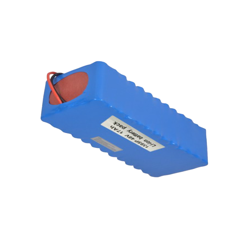
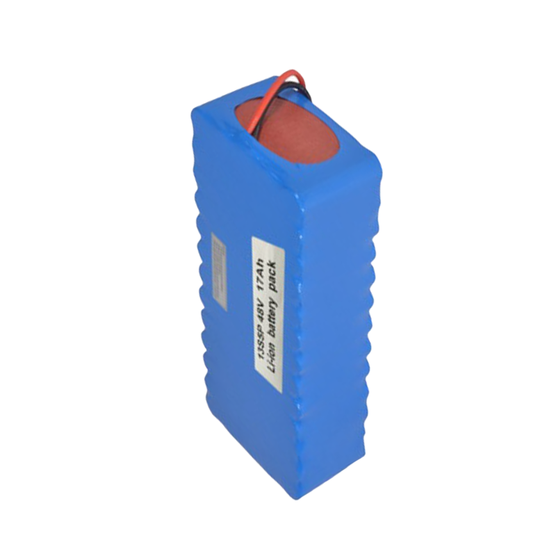
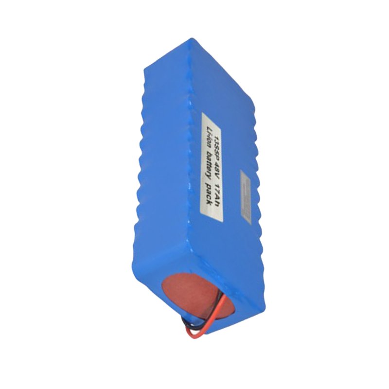
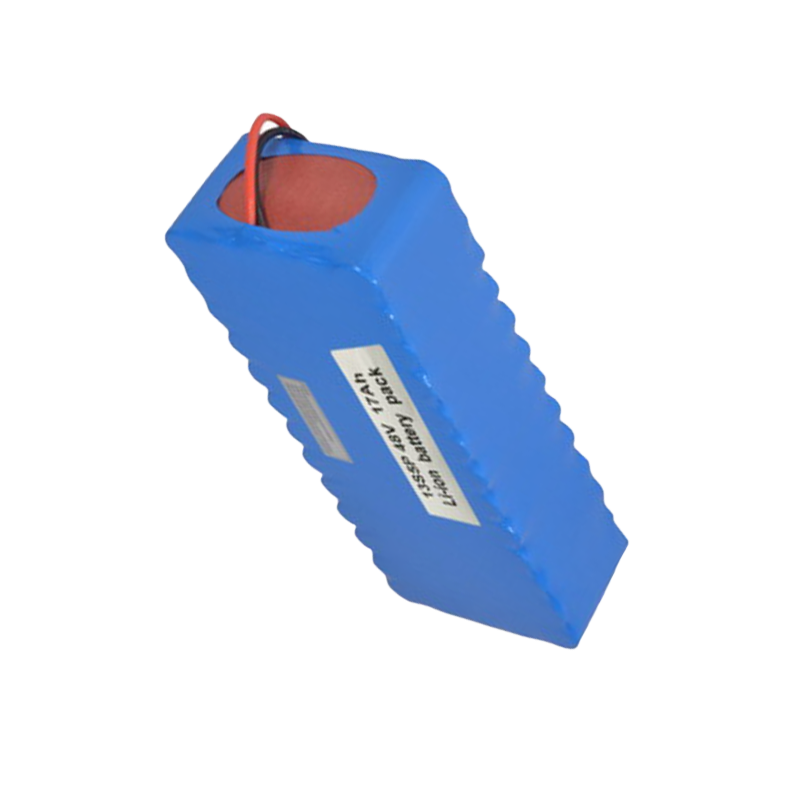
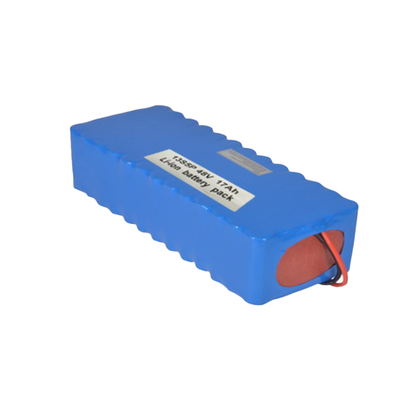
| Battery Type | Li-ion |
| Nominal Battery Voltage | 48V |
| Nominal Capacity | 10.4Ah |
| Nominal Energy(25℃,0.2C) | 499.2Wh |
| Maximum In Series | 13 Series |
| Maximum In Parallel | 4 Parallel |
| Charge Voltage | 54.6V |
| Max Charge Current | 10A |
| Max Discharge Current | 20A |
| Service life | more than 500 cycles |
| Working Temperature Range | Charge: 0℃–+45℃ Discharge: -10℃–+60℃ |
| Storage Temperature | -20℃–45℃ |
| Storage Duration | 6 Months at 25℃ |
| Packing | Customized |
| Basic Solution | Over Charge Protection,Over Discharge Protection,Over Current Protection,Over Voltage Protection,Under-Voltage Protection,Temperature Protection,Short Circuit Protection |
| Dimension | L240*W78*H86mm |
| Weight | Approx.2.86kg |