- Industries


Home Backup & Garden BMS
View More >
Electric Forklift BMS
View More >
Golf Cart BMS
View More >
Electric Two-wheeler BMS
View More >
Aviation & UAV BMS
View More >
BMS For Power Tools
View More >
Medical Equipment BMS
View More >


AYAA offers high-quality 6S battery management systems for car starting and parking air conditioners. We provide wholesale options, OEM/ODM services, and reliable factory supply.
As lithium-ion battery technology powers an array of applications from consumer electronics to drones, electric tools, and portable energy storage, the 6S Battery Management System (6S BMS) has become pivotal in ensuring safety and performance. Designed for six series-connected lithium cells (typically 22.2V nominal), the 6S Battery Management System provides robust protection against overcharge, over-discharge, and short circuits while optimizing cell balance and efficiency through advanced voltage monitoring and balancing mechanisms. This guide offers a detailed exploration of the 6S Battery Management System, covering its working principles, internal architecture, key features, and practical applications. Whether you're an engineer, DIY enthusiast, or renewable energy manufacturer, this article provides actionable insights into leveraging the 6S Battery Management System for reliable, high-performance battery solutions.
A 6S Battery Management System is a specialized circuit designed to manage and protect a battery pack consisting of six lithium-ion cells in series, typically delivering a nominal voltage of 22.2V (or 19.2V for LiFePO4). The 6S BMS monitors critical parameters such as voltage, current, and temperature to prevent hazardous conditions like overcharge, over-discharge, and short circuits, ensuring both safety and longevity of the battery pack.
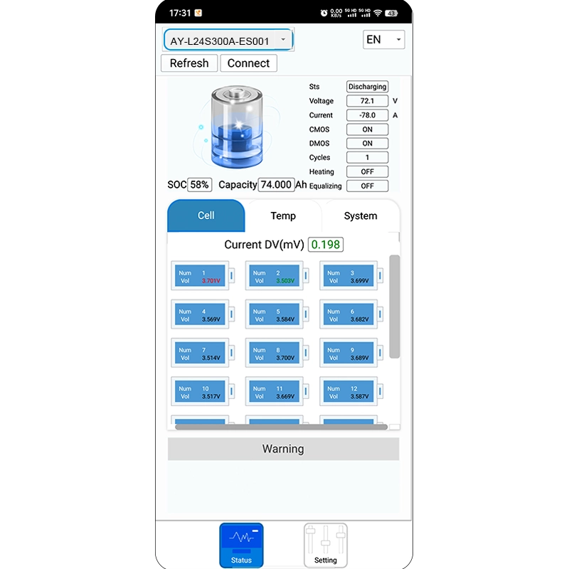
In applications such as electric tools, drones, lightweight electric vehicles, and portable power stations, the 6S Battery Management System is essential for maintaining system stability under demanding conditions. Compared to 1S–4S systems, the 6S BMS handles greater complexity due to higher cell counts, requiring sophisticated protection and balancing strategies to manage voltage deviations. Many 6S Battery Management Systems also support communication protocols (e.g., UART, I2C, CAN Bus), enabling integration with host systems for real-time data reporting, SOC (State of Charge) display, and remote diagnostics.
The 6S Battery Management System operates through a closed-loop control mechanism that combines real-time monitoring, intelligent control, and dynamic balancing to ensure safe and efficient operation. Its core functions include:
Each of the six cells is connected to the 6S BMS via sampling lines, allowing periodic voltage measurements:
The 6S Battery Management System employs passive or active balancing to minimize voltage differences between cells:
This continuous monitoring and balancing ensure the 6S BMS maintains cell voltage consistency, enhancing battery lifespan and performance.
The 6S Battery Management System is a highly integrated circuit comprising several critical components:
1. Microcontroller (MCU)/BMS IC: Chips like TI’s BQ series or local brands (e.g., Fuman, Lingyang) handle core logic.
2. Voltage Sampling Circuit: Multi-channel ADCs measure individual cell voltages.
3. Temperature Sensors: NTC thermistors provide thermal monitoring and protection.
4. Current Sensing: Precision resistors or Hall-effect sensors detect overcurrent or short-circuit conditions.
5. MOSFET Switches: Control charge and discharge paths, acting as the 6S BMS’s execution unit.
6. Balancing Module: Includes resistors and drivers for passive or active balancing.
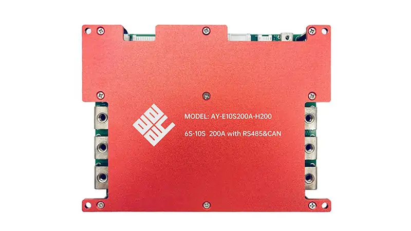
7. Communication Interfaces: UART, RS485, or CAN for remote monitoring and configuration.
High-quality 6S Battery Management Systems use four-layer PCBs to reduce noise and improve thermal management. Industrial-grade models incorporate TVS diodes and PTC fuses to protect against voltage surges and ESD, ensuring reliability in harsh environments.
The 6S Battery Management System is designed to protect and optimize battery performance through:
These features make the 6S Battery Management System indispensable for high-density, long-cycle applications.
The 6S Battery Management System supports a 22.2V platform, making it ideal for mid-to-high-power applications:
Advanced 6S Battery Management Systems with Bluetooth or CAN Bus offer app-based control and data visualization, enhancing user experience in smart applications.
Correct installation of a 6S Battery Management System is critical for safety and performance. Below is a detailed guide:
1. Verify Cell Condition: Ensure all six cells have voltages within ±0.05V to prevent initial protection triggers.
2. Wiring Sequence: Connect from B- (total negative), B1, B2, to B6 (final cell positive). Avoid skipping or reversing connections.
3. Connect P-/C- Ports: Link P- to discharge output and C- to charging (some 6S BMS units combine these). B+ is the common positive.
4. Initialize: Activate the 6S BMS via charger or app/button (if applicable).
5. Configure Parameters: For smart 6S BMS, use software to set overcharge (e.g., 4.20V), over-discharge (2.80V for Li-ion, 2.50V for LiFePO4), and current thresholds.
Use a multimeter to verify connections before powering on to avoid short circuits or damage.
To ensure safe operation of a 6S Battery Management System, adhere to these precautions:
1. Enable Protection Settings: Verify overvoltage (4.20V) and undervoltage (2.80V for Li-ion) thresholds are active.
2. Match Battery Pack: Use a 6S BMS with a proper 6-series configuration; avoid mismatched or aged cells.
3. Use Compatible Chargers: Select chargers with current limits matching the 6S BMS specifications to prevent MOSFET wear.
4. Control Operating Environment: Avoid high temperatures (>60°C), humidity, or vibrations. Add thermal pads or cooling for heat dissipation.
5. Periodic Cell Checks: Measure cell voltages every 3–6 months to ensure balancing effectiveness and detect cell degradation.
These measures prevent accidents and extend the lifespan of the 6S Battery Management System and battery pack.
Common issues with a 6S Battery Management System include voltage imbalance, charging failures, and communication errors. Here’s how to troubleshoot:
Regular maintenance and correct installation minimize these issues, ensuring reliable 6S BMS performance.
Choosing the right 6S Battery Management System in 2025 requires evaluating brand reliability, features, and cost-effectiveness. Top brands include:
Verify compatibility with Li-ion or LiFePO4 cells and check specifications for voltage, current, and certifications (e.g., CE, UL1973).
Understanding the differences between 4S, 6S, and 8S Battery Management Systems is crucial for matching voltage and application needs:
|
System |
Li-ion Voltage |
LiFePO4 Voltage |
Applications |
| 4S | 14.8V | 12.8V | E-skateboards, battery boxes |
| 6S | 22.2V | 19.2V | Drones, tools, portable power |
| 8S | 29.6V | 25.6V | E-bikes, medical devices |
Choose a 6S Battery Management System for mid-power applications, ensuring compatibility with controllers and motors.
The 6S Battery Management System is the cornerstone of safe and efficient 6-series lithium battery management, delivering precise protection, intelligent balancing, and robust communication. From electric tools to drones and portable power, the 6S BMS ensures optimal performance and longevity. By understanding its principles, selecting the right model, and following proper installation and maintenance practices, users can harness the full potential of the 6S Battery Management System in modern lithium-ion applications. As IoT and smart hardware advance, the 6S BMS will continue to evolve, driving smarter, safer, and more efficient battery solutions.
| LF | LI | |||
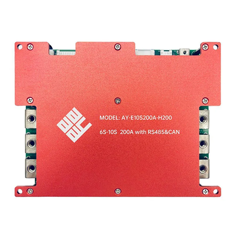
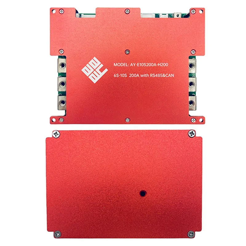
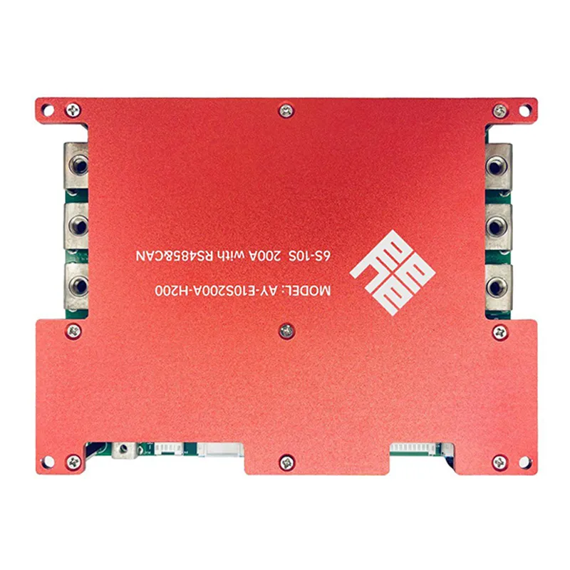
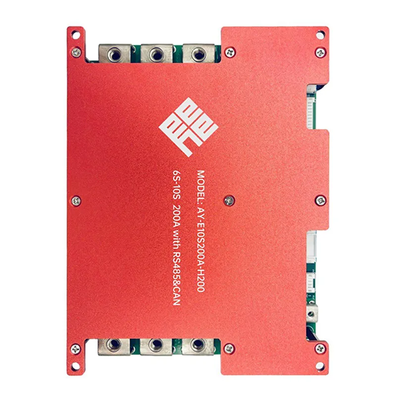
| Model Number | AY-LS10S200A-H200 (6S-10S) | |||
| Communication Interface | RS485/CAN/UART | |||
| Charging voltage | DC:19.2V~32V CC/CV(3.2V/Cell) 6s~10s |
DC:25.2V~42V CC/CV(4.2V/Cell) 6s~10s |
||
| Maximal continuous charging current | 200A | |||
| Maximal continuous discharging current | 200A | |||
| Current consume in normal operation | ≤30mA | |||
| Current consume in sleep operation | ≤150uA | |||
| Balance voltage for single cell | 3.6±0.05V | 4.2±0.05V | ||
| Over charge detection voltage | 3.65±0.05V | 4.25±0.05V | ||
| Charge Over current detection current | 220±3A | |||
| Discharge Over current detection current 1 | 450±3A | |||
| Discharge Over current detection current 2 | 600±3A | |||
| Short Protection | YES | |||
| SOC | 5%~8% | |||
 |
|
| Size | L200 * W150 * T34 mm |
| NTC | 10K |
| Temperature switch | / ℃(the batteries temperature) |
| Weak current switch | YES |
| Active balance | / |
| Heater | YES |
| Braking Resistors | / |
| Low temperature protection when charge | 0℃ | ||
| Release temperature( low temperature protection) | 5℃ | ||
| Over temperature protection when charge | 60℃ | ||
| Release temperature( over temperature protection) | 55℃ | ||
| Low temperature protection when discharge | -15℃ | ||
| Release temperature( low temperature protection) | -10℃ | ||
| Over temperature protection when discharge | 65℃ | ||
| Release temperature( over temperature protection) | 55℃ | ||
| Operating Temperature Range | -40~+85℃ | ||
| Storage Temperature Range | -40~+125℃ | ||
| LCD display screen | / |
| LED light board | / |
| Bluetooth mode | / |
| 4G | / |
| GPS | / |